
Basic Ground System Functions
A ground system provides four primary functions:| To help disperse or divert energy from lightning strikes | ||
| To provide safety in case some problem or fault energizes the cabinet or chassis of equipment with dangerous voltages | ||
| To provide a controlled RF return path for end-fed (single wire feed) or poorly configured or improperly designed transmission-line fed antennas | ||
| To provide a highly conductive path for induced or directly coupled radio-frequency currents, rather than having them flow in lossy soil |
If the antenna system has bad common mode current problems, caused by a faulty design or installation, a ground can help reduce common mode noise reaching the antenna. This is really from an antenna flaw, and not from the "reflection of signals".
A ground screen, counterpoise, or ground radial system below the antenna can reduce local noise sensitivity by reducing the antenna's response to local noise. This would apply to a horizontally polarized antenna, because earth losses can cause the wave to tilt and have vertical response. As we all know, vertically polarized signal propagate along the earth with much less attenuation than horizontally polarized signals. Ground rods have no effect on this, it requires something that actually covers the lossy earth under the horizontally polarized antenna.
A ground will NOT.....
- A ground normally will not help reception. The exception is an antenna system design problem or installation problem causing the antenna system to be sensitive to common mode feedline currents. If adding a station ground helps reception or transmission, there is an antenna system flaw.
- A ground will not reduce the chances or number of lightning strikes. A properly installed and bonded entrance ground can only reduce or eliminate lightning damage from hits.
Lightning Ground
Lightning is a high energy stepped waveform pulse. Rapidly changing steps in voltage contain high frequency energy. This energy has a peak in the dozens or hundreds of kilohertz, with the bulk of energy ranging from low AC frequencies to perhaps 1MHz. Damaging energy extends to hundreds of megahertz. Lightning should be considered a dc to VHF energy source with the bulk of energy at lower frequencies. Current is massive, thousands of amperes can flow in a lightning strike. A good ground must have a very low impedance over a very wide frequency range. This rules out thin wires, and loosely woven braided conductors should be avoided. The very best ground leads are solid wide smooth surfaces, although braiding sometimes must be used in areas that demand conductor flexibility.
Most of the time damage comes from lightning strikes on power lines. Lightning most often follows the utility lines to the house, through house wiring to equipment, and to ground in antenna systems. The real danger is lightning flowing through the equipment and house wiring to seek a ground. Read this page link station ground
With taller towers, lightning can be a frequent unwelcome visitor. Tall structures often require a large-area ground with low impedance, wide, smooth copper flashing or heavy gauge solid wire surrounding critical areas, such as a work area or equipment area near the tower base. Tall towers need a ground that rapidly and evenly spreads charges out over a wide area. The goal is to prevent objects near the structure from rising significantly faster in voltage than other objects located near the tower. Very high currents can flow between things near the tower, it is important to provide a low-impedance path for these currents.
Lightning grounds should always provide a common low impedance path between everything conductive entering a building. This means power lines, telephone lines, TV antennas, and metallic conduits or pipes should all share a common ground connection buss that has very low impedance. Normally the lowest impedance connection is provided by a wide smooth surface copper flashing, although very heavy round copper can be used. Round copper has lower RF resistance per unit length for a given surface area, but flat wide copper has less reactance and lower overall impedance. This is because fewer magnetic flux lines encircle any given area of wide strip than enclose the surface area of a compact conductor. In effect the magnetic field is "spread out", reducing inductance.
There are many sites detailing ground connections, Polyphaser being the most accurate overall.
A good lightning ground is generally a good equipment fault safety ground, but it might not be a good RF ground! RF grounding sometimes requires shielding of the earth from radio frequency fields, or moving the RF energy out of the lossy soil. Lightning generally requires we connect to the earth, and freely move energy into or out of lossy soil. Certain RF ground applications require minimizing RF current flowing into lossy soil.
Grounds at Towers
Permanently grounded towers like Rohn 65G.
Each leg of the tower base is grounded to the ground system that consists of at least thirty fairly-long #16 buried bare solid copper wires.
There is also a buried #8 AWG solid copper wire from each corner rod extending outwards.
Soldering is "hard" silver solder, not plumbing type silver solder. It takes a MAP gas torch to melt real silver solder. The copper almost gets red hot when soldering. Silver solder is available from McMaster-Carr or from welding supply houses.
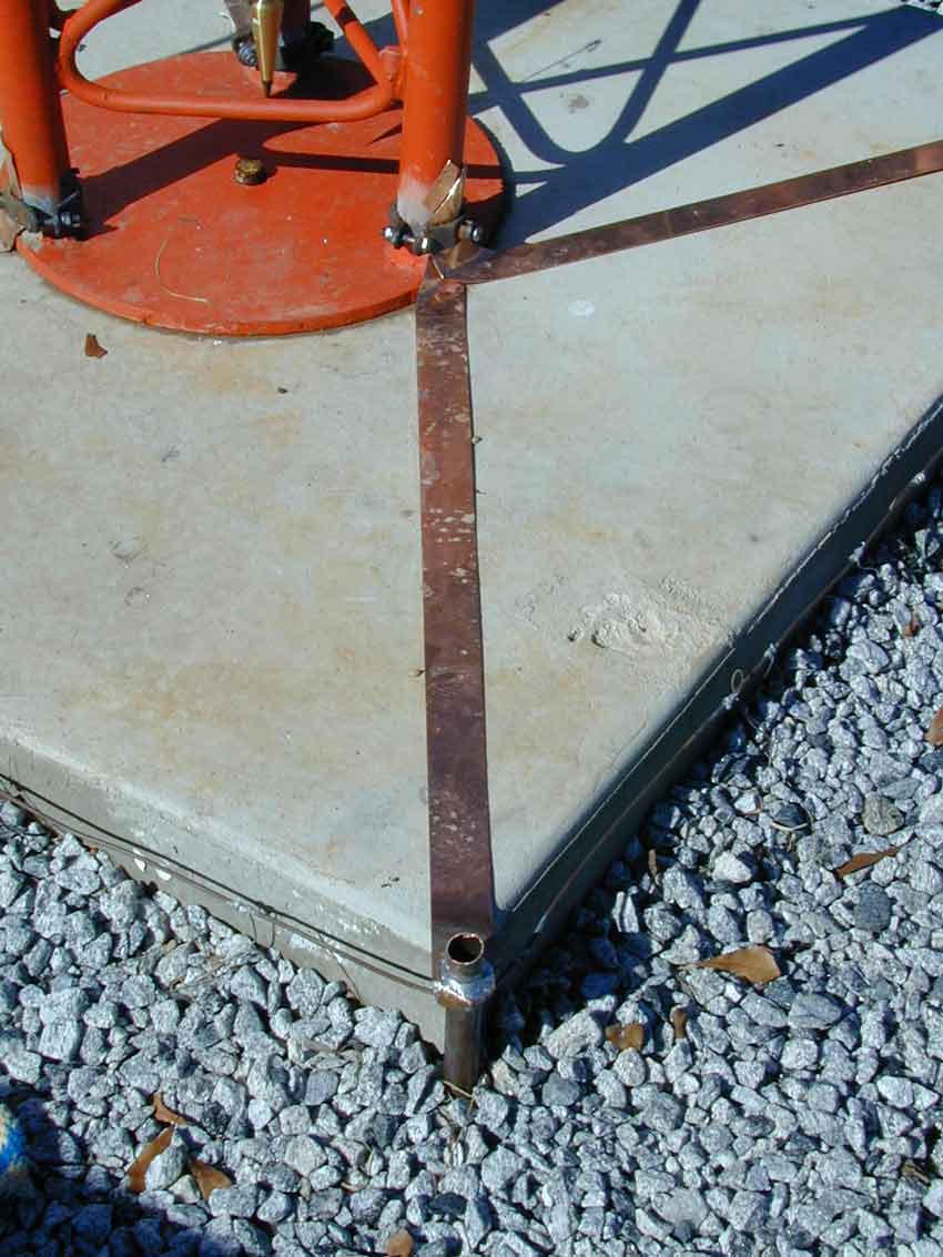
Insulated Towers
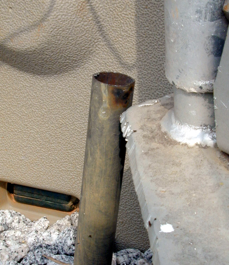
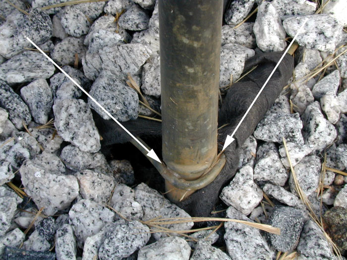
3/4-inch copper pipe at all three corners of the base plate serve as a lightning gap on my insulated base Rohn 45g tower.
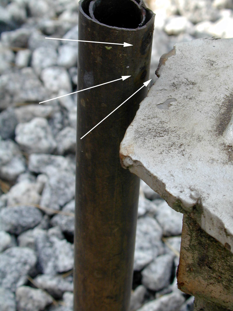
The arrows point to burned marks where lighting has caused arcs across the gap.
I bend the pipe in or out to change the gap.
The ground buss of this tower has one hundred 200-ft long radials attached. The radials are #16 AWG solid tinned copper buss wire.
Ball Gap Lightning Gap
My 300-ft tall Rohn 55G has a ball gap at the base.
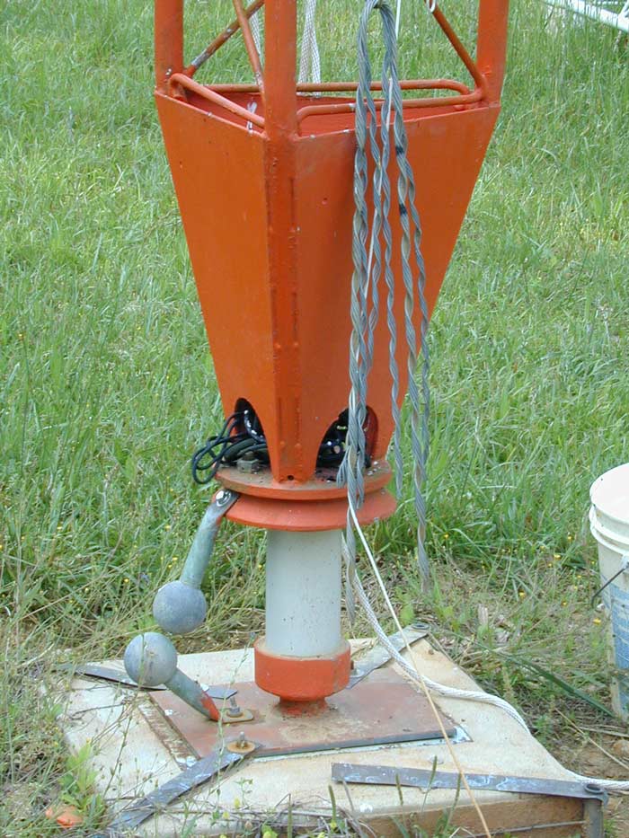
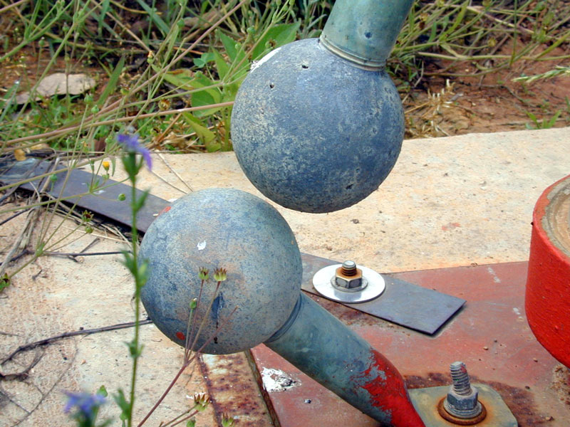
This is the much preferred commercial method.
At House
By the way, despite having two 300-ft tall towers, four 130-ft wire verticals in a four square, a 220-ft tower, a 200-foot rotating tower, and miles of receiving feedlines covering distances up to 3/4 mile... I don't use coaxial lightning surge protectors. I have bulkhead entrance panels and use common point grounds and a few MOV's on power lines, but none of my feedlines have surge suppression devices. All of my feed and control cables stay connected during lightning storms, last count that was about 50 cables. My equipment stays connected to power mains through a main disconnect switch.
The sole source of my transmitting antenna disconnects is an unmodified DX Engineering RR-8 HD antenna switch.
The case is securely grounded to the hamshack entrance ground.
I fabricate my own copper grounding plate for use at cable entrances:
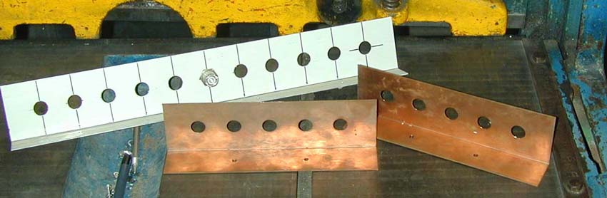
Every cable enters through bulkhead connectors attached to a plate like those above. This plate is tied into the common ground at my station entrance. That ground is common with power line and utility entrance ground to the house.
Despite multiple hits every year on my tall tower, I never suffer equipment damage. This is all due to my use of proper grounding protocol. Everything entering my operating room, including power line safety grounds, bonds to a single point at the entrance point of my operating tables.
Safety Grounds
Radios that operate from power mains stand a chance of having the power line accidentally fault to the chassis. Worse yet, a linear amplifier with high voltage power transformer might develop a secondary to primary short, and that short might cause the chassis to rise to peak secondary voltage plus peak primary voltage! An amplifier with a 2400 volt RMS transformer operating on 120 or 240 volt USA power mains might have a chassis voltage as high as 3600 volts from a secondary to primary failure inside the transformer.
Any advice saying our equipment doesn't require a safety ground connection is very bad advice. All power mains operated amateur radio gear, especially devices with HV inside, requires a safety ground.
The safety ground does not really need a ground rod, it actually only requires a connection back to the power mains service entrance ground though a very heavy conductor. It may be desirable to augment this safety ground connection with a few extra earthing ground rods. As with lightning grounds, any special safety ground must bond to the utility entrance ground. A good lightning entrance ground also makes a good safety ground, provided it is brought from the entrance point panel to the operating area where equipment is bonded into the ground. Do not go outside beyond the entrance panel barrier with this ground lead.
Equipment with properly installed safety ground plugs, provided wiring and plugs are up to current codes, do not require a special safety ground connection. They are grounded through house wiring.
RF Return-path Ground
An antenna system using properly installed and connected coaxial or balanced lines would never require a RF station ground. All currents flowing out to the antenna would be perfectly matched by equal currents flowing back on the second conductor, be it a shield or the second identical conductor of a balanced line.The problem is many antenna feedpoint or feed systems are poorly designed. It is the abundance of poorly designed systems that cause problems. These flawed systems are behind notions that good Ham shack RF grounds are required to reduce TVI, prevent RF in the shack, or improve transmitting or receiving ability. The troublesome currents are called common-mode currents, because they are not normal push-pull transmission line currents found in two-conductor transmission lines, like coaxial or ladder lines.
A few examples of antennas producing excessive RF in-shack ground currents:
| End-fed halfwaves, including end-fed "dipoles" of all types | ||
| Zepp antennas, especially those where the feedline is not an odd 1/4 wl and the antenna not a multiple of 1/2 wl) | ||
| Center fed dipole antennas without a balun or dipoles that do not use a feedline length that minimizes common-mode current | ||
| Verticals with poor grounds or somewhat sparse grounds, including "half-wave" verticals with small or no radial systems | ||
| End-fed longwires, off-center fed dipoles, or Windom antennas |
An RF "return path" ground or antenna system ground requires low RF impedance. The ground has to spread current around over a large area. The best system uses many small diameter conductors radiating out at least 1/8th wave, and preferably further, from a central connection point. These conductors do not need to contact earth, they function simply by providing "electrical mass", or a low RF impedance, for the antenna system to push against. It is not a question of surface area or capacitance, it is a question of distributing charges efficiently over a large spatial area (large in terms of the operating wavelength).
Induced Ground Currents
All efficient antennas, including loops, dipoles, verticals, and beam antennas, are surrounded by very strong electric and magnetic fields. If the antenna is close to earth (in terms of operating wavelength) considerable current can flow in the lossy soil. Current flowing in lossy earth causes power loss, even when the antenna and/or ground system does not have a direct earth connection. Earth currents are especially problematic when dipoles are placed at small fractions of a wavelength above ground, or when verticals are mounted on or near the earth's surface.
Currents like are minimized by covering a large area of earth surrounding the antenna with many closely-spaced conductors. The conductors do not need to be any particular length, they only requirement is they extend beyond the area where field density is high. If the conductors are less than .05 wavelength apart, they can be considered a large single conductor covering the entire area. Much wider spacing than .05wl, and they allow the lossy media between the conductors to be exposed to strong fields.
The diameter or gauge of grounding system conductors isn't important, but spacing of grounding conductors and overall length of grounding conductors are both very important!
Isolating or Disconnecting Feedlines
One of the best ways to protect receivers and transmitters, besides having a good ground system and cable entrance feedthrough that is bonded to the mains ground, is to disconnect the feedline from the equipment. This disconnect has to be done properly. The best location is normally away from the operating desk, right near the entrance.
If you use disconnect relays or switches, they should be a double-make double-break style. A double-make double-break looks like this:
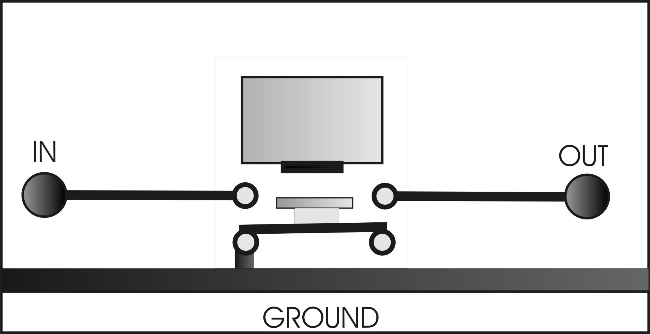
Lightning cannot pass through from side-to-side because the shorting bar is grounded when not energized. Any arcs across contacts would go to ground.
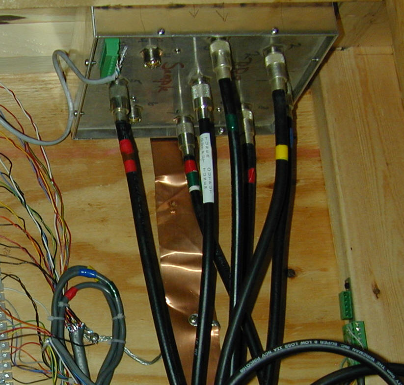
As an example of a layout with proper grounding, you can see my station entrance system below:
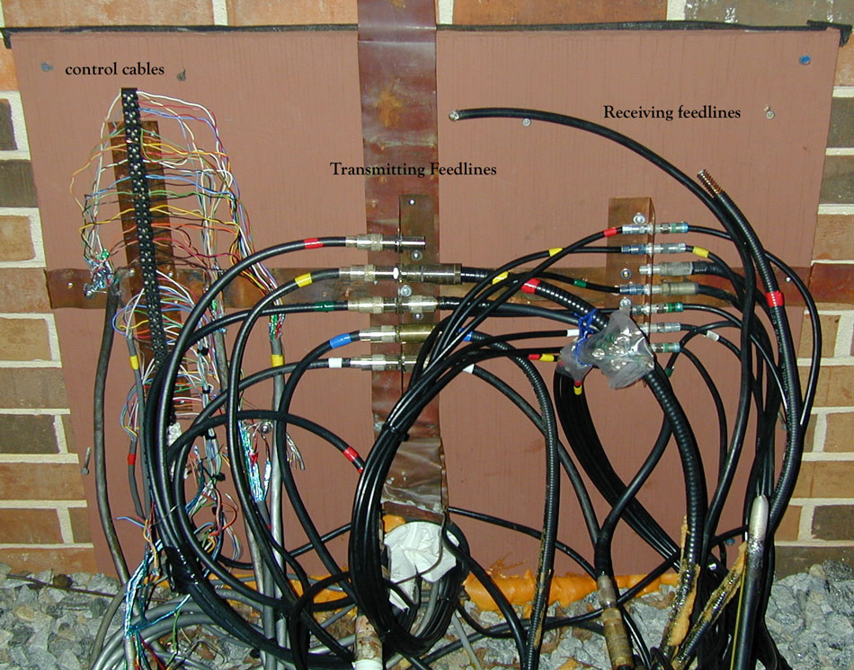
This is my house entrance. It is normally covered with a box to prevent weather and sun exposure, to visibly hide the wires, and to prevent physical damage.
All cables are shielded and the shields are grounded outside the house. The large copper flashing routes directly under the house to the power mains entrance ground.
Control cables are to the left, transmitting feedlines are in the middle, and receiving antennas are to the right.
There are spare cables also.
Inside House
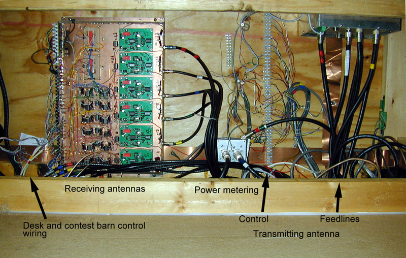
All transmitting antennas enter through a DXE RR-8 antenna switch. The switch case is grounded through large copper flashing that ties the station power lines and receiving antennas to a common buss in the room entrance box.
Cable shields are bonded to that buss.
Receiving antennas are to the left, and are grounded to the same flashing.
My station antenna disconnect is actually a DX Engineering RR-8 antenna switch. The RR-8 switch, like the Ameritron RCS-8V, provides excellent center conductor isolation whether the switch is configured to ground the center conductor or not. This is because both the DXE and RCS-8V use a double-make double-break isolation system. I like the DXE RR-8 better because it has an all metal cabinet that is easier to ground.
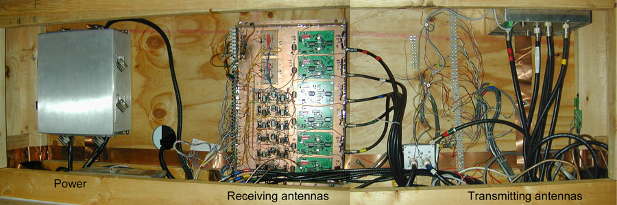
This box (I pieced together two photos to show it all) looks like a window seat when the cover is on. Power and telephone entrance is on the left, receiving antennas are in the middle, and transmitting antennas are on the right. All grounds and shields are tied together with wide flashing.
No comments:
Post a Comment