
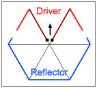
The Hexbeam is a great little antenna! It should be high on your list of options if you want a design that can be "multi-banded", exhibits useful gain and directivity, is very lightweight, has a small turning radius, and which lends itself readily to "Do It Yourself" construction. Please note that the term "Hexbeam" is used on this site in the generic sense of a directional wire antenna that can be conveniently suspended on an hexagonal support structure. It does not refer to the Hex-Beam® manufactured by Traffie Technology of Ashby, MA USA. I first got interested in the Hexbeam after seeing it described on various websites, but I was puzzled by conflicting sets of published dimensions and hearing that some constructors were disappointed by the Front-to-Back performance they were getting. That led me on a quest to try to understand the Hexbeam better. After hundreds of hours computer modelling, and many more hours building and testing prototypes, I think I understand it a little better. These web pages are a record of what I learned; I hope they will give you a detailed insight into how the antenna works, will encourage you to construct one for yourself, and will help you get the best out of it if you do. In the Autumn of 2007, my computer modelling and practical experiments led to a new design of Hexbeam which, for a modest increase in size, provides a significant improvement in performance and SWR bandwidth over the traditional design. It was the subject of an article I wrote for the December 2007 edition of Antennex - the on-line magazine for antenna experimenters. To distinguish between the two designs on this website, the new antenna will be referred to as the "G3TXQ Broadband Hexbeam" and the traditional will be called the "Classic Hexbeam". There is a section devoted to each of the two designs, followed by material that is relevant to Hexbeams in general. I am indebted to Leo (K4KIO) and Holger (DL7IO) for producing websites that first excited my interest in the Hexbeam. They have been very supportive in my efforts to get a better understanding of how the Hexbeam works - at the last count Leo and I had exchanged over 500 Emails! Although these pages contain some photographs of my own Hexbeams, they do not provide detailed constructional information. If you need guidance on making one, you should visit Leo's website where you will find step-by-step instructions for building the Broadband Hexbeam or, if you wish, the older Classic design. A number of commercial companies can supply parts or complete antennas, including: If you want to keep up to date with what's going on in the Hexbeam world you should take a look at the Yahoo special interest group. Although much of the discussion in these pages is based on my practical experiments, a lot is also the result of simulating the Hexbeam's performance using EZNEC+; I have therefore included two pages on modelling the Hexbeam which demonstrate that the results obtained through simulation are borne out in practice. Unless otherwise stated, performance parameters are quoted for a Free Space environment and Gains are quoted referenced to an Isotropic radiator (dBi). This approach is convenient because it allows antennas to be evaluated on a "level playing field" without needing to consider the effect of the local environment (height above ground, ground conductivity, etc); it is also consistent with the way most commercial antenna manufacturers choose to quote their data. However the "real world" will modify the results that you get in practice. For example, I have found that on-air testing of F/B ratios with DX stations consistently produces figures that are around 10dB higher than predicted by Free Space modelling. This does not invalidate Free Space modelling - but it means you have to be careful how you interpret the results! Finally, don't let the volume of data on these Hexbeam pages put you off having a go at constructing one - K4KIO's website has step-by-step instructions - I'm sure you will be pleased with the results. I would welcome questions or comments on this material. Mail me at: hexbeam{at}karinya.net This section of the website describes the new Hexbeam design which I developed in the Autumn of 2007. It was the subject of an article I wrote for the December 2007 edition of Antennex - the on-line magazine for antenna experimenters. The unique feature of the new design is a revised shape of Reflector, shown on the right, which significantly extends the performance bandwidth and improves the SWR, at the cost of a 17" increase in turn radius on a 20m version. For clarity we refer to the new design as a "Broadband Hexbeam", and to the conventional design as a "Classic Hexbeam". The chart on the right shows how the Broadband Hexbeam compares with a Classic Hexbeam on 20m, and the table shows how the performance of the Broadband Hexbeam stacks up against a couple of popular commercial 5-band HF beams - the comparably sized Cushcraft MA5B and the much larger, "full size", HyGain TH11DX Here are some audio clips which demonstrate the F/B performance of the new design. They comprise 3-5 seconds with a beam pointed towards a DX station, interlaced with 3-5 secs with a beam pointed in the opposite direction. Interestingly, analysis of the audio waveforms suggests that the F/B ratios are in excess of 30dB - a higher figure than I measure with a line-of-sight source on my test range. Hexbeam F/B 20m Iceland And here is a clip demonstrating the difference between my Broadband Hexbeam at 20ft and my 132ft inverted V doublet with its centre at 20ft. The first half of each 10 second period is the Doublet and the remaining period is the Hexbeam. A half second gap has been inserted to emphasise the changeover. This table shows the recommended dimensions for a 5-band Broadband Hexbeam constructed from #16 or #14 bare copper wire. The band feedpoints are interconnected with 50 Ohm coax, and the array is Top fed. This 5-band design requires a horizontal distance of about 130" from the Centre Post to the tips of the spreaders. If you are unable to accomodate this increased size, don't be tempted to stick to the smaller Classic shape for 20m and adopt the new shape for 17m thru 10m: modelling shows that the 20m performance bandwidth suffers dramatically, probably due to the mid section of the 17m Reflector providing an RF coupling path between the "knees" of the 20m Reflector. Although this site contains some photographs of my own Broadband Hexbeam, it does not provide detailed constructional information. If you need guidance on making one, you should visit Leo's (K4KIO) website where you will find excellent step-by-step instructions. Max-Gain Sytems in the USA also do a complete kit of fibreglass tubing for the Broadband Hexbeam. The design has now been adopted by a significant number of constructors, and these dimensions are proving to be robust and repeatable. WY3A, is one such constructor who is now enjoying the fruits of his labour - take a look at Bill's website and the photographs of his G3TXQ Broadband Hexbeam. A number of constructors have enquired about dimensions for 30m or 40m versions of the antenna; they are shown in the next table. They assume the antenna is constructed from #16 gauge bare copper wire, and that connector blocks are used to join the wire elements to the tip-spacing cords. Please note that these dimensions are the result of computer modelling exercises - I have not yet built antennas to confirm them. A consequence of the Classic Hexbeam's geometry is a relatively narrow performance bandwidth; typically the F/B exceeds 10dB over a band equivalent to only 1.4% of the centre frequency, and the SWR is above 2:1 for a significant proportion of this band. This narrow bandwidth is largely determined by the Q of the Reflector which I measured at about 30 for a 10m element constructed from #16 wire. Compare this with a linear dipole which has a Q of about 10. I reasoned that if I could find a way of reducing the Q I should end up with a broader-band antenna. I spent many hours modelling Reflectors and evaluating ideas on a 10m testbed - you can see the detail on the Reflector Experiments page. I tried using thicker wire of various types, including 2 varieties of coaxial cable and "caged" wires. I also tested alternative Reflector shapes. Of all the ideas evaluated, by far the most effective and easiest to implement was to change the shape of the Reflector. Even when using relatively thin #16 wire the new shape has a radiation resistance of 44 Ohms and a Q of about 17. It requires an increase in turning radius of about 15%. Modelling a Hexbeam with this geometry produced very encouraging results: F/B > 10dB and SWR < 2:1 across all of the 20m, 17m, 15m and 12m bands, and approximately 1 MHz of 10m. The modelling suggested there was little to be gained by making the same change to the shape of the Driver element; in fact, retaining the classic shape for the Driver delivers a better match to 50 Ohms and avoids a further increase in the turning radius. Constructing and testing a 10m monoband version of the new antenna confirmed the modelling results, and so a full 5-band test beam was constructed. The 20m, 17m and 15m results were immediately satisfactory, but it took some time to optimise the 12m and 10m performance; the proximity of these bands often causes problematic interactions which are not always predicted by the modelling, and the final wire dimensions for these bands were a result of "cut and try" on the testbed. The following charts show the measured performance of the 5-band prototype with the baseplate at a height just under 20ft. At this height, ground reflections cause the 10m and 12m peak F/B figures to be suppressed compared to the Free Space values, and the 20m and 17m figures to be enhanced. On this page we will explore some of the technical details behind the Broadband Hexbeam. In particular we will look at which of the antenna dimensions are critical to particular performance parameters. Here's the "Executive Summary": The principles behind Hexbeam operation are no different than those of any 2-element "parasitic" beam. One element - approximately half a wavelength long - is "driven" by the transmitter; the other - also about a half-wavelength long - is placed close to the driven element. As a result of its proximity, currents are induced in this second element which result in power being re-radiated from it; because it is not driven directly this element is called "parasitic". The relative magnitude and phase of the currents in the parasitic element result in the "re-radiated" power reinforcing the power from the Driver in some directions, whilst cancelling it in others - hence the antenna becomes "directional". In a Broadband Hexbeam the Front-to-Back ratio peaks at a frequency about 0.7% above the self-resonant frequency of the Reflector. The Azimuth plot on the right shows the directionality that is typical of the antenna. The challenge to the antenna designer is to control the "mutual coupling" between the elements in such a way that the relative magnitude and phase of their respective currents optimises the antenna's performance. In the case of the Hexbeam this "mutual coupling" is controlled partly by the general spacing between the elements, and, critically, by the gap between the tips of the Driver and Reflector. If the designer had total control of the relative magnitude and phase at all frequencies, excellent Hexbeam performance would be possible over a wide bandwidth - gains in excess of 6.8dBi (4.7dB more than a dipole) and F/B ratios over 40dB. But of course in the "real world" such control is not possible, so before getting too carried away we need to manage our expectations! The chart on the right shows the modelled performance of a full-size 2-element 20m monoband yagi in Free Space; it makes a useful reference for judging the performance of the Broadband Hexbeam. This Yagi has a 386" Driver, a 418" Reflector, and a 133" boom length (0.16 wavelengths) - a typical design compromise between Gain, Front-to-Back ratio (F/B) and a reasonable match to 50 Ohms. The antenna has an 18.3ft turn radius and is assumed to be constructed from 3/8 inch diameter aluminium. We see that the full size Yagi is a relatively broadband antenna. The Gain falls by only 0.7dB across the 20m band and never falls below 5.8dBi. The F/B varies by only 1dB across the band, peaking at 11dB. On the other hand, the SWR varies significantly from 2.1 at the lower band edge to 1.0 at the top of the band. So, what can we reasonably expect from a Broadband Hexbeam just over half the Yagi's size? This chart shows the performance of a typical 20m monoband Broadband Hexbeam. Each Driver leg is 219.5" long and the total Reflector length is 415"". The spacing between the Driver and Reflector tips is 24" and it is constructed from #16 gauge bare copper wire; it has a turn radius of 10.7ft. The dimensions were chosen to provide a good compromise between Gain, F/B and SWR. This antenna will be used as a benchmark as we explore the effect that various dimensions have on Broadband Hexbeam performance. The first thing we see is that the Hexbeam has less Forward Gain than the Yagi, and the Gain falls by 1.2dB across the band - a result that is typical of end-coupled wire beams. Neverthless, the Gain is never worse than 1.4dB (1/4 of an S point) below the Yagi and we might think this is a reasonable price to pay for the reduction in size. The Hexbeam beats the Yagi "hands down" for F/B across the band, reaching a peak of 26dB and never falling below 14dB. What's more the SWR is "well-behaved" with a minimum of 1.4, rising to 1.7 at the band edges. A nice feature of the Broadband design is that it allows us to place minimum SWR at the same frequency as peak F/B. For a relatively small antenna, the Broadband Hexbeam holds up well against the Yagi and it compares very well with commercial HF mini-beams. For example, according to figures published by Cushcraft, the 20m Gain of the MA5B is 3.6dBi and its 2:1 SWR bandwidth is 90 KHz. Now let's explore which of the Broadband Hexbeam's dimensions are critical, and how they affect its performance. The length of the Reflector on a Broadband Hexbeam has little effect on Gain and peak F/B, but it has a pronounced effect on the tuning of the beam (i.e. the frequencies where it delivers maximum Gain and best F/B ratio). It also has some effect on the SWR, as a result of the Driver / Reflector ratio changing, but it is small compared to the effect on tuning. If we change the length of the Reflector on our reference antenna from 411" to 419" in 2" steps and plot the F/B ratio at each step, we get the results shown on the right. We see that for each 2" increase in Reflector length the frequency of peak F/B drops by about 68 KHz. And because 2" represents 0.5% of the total length, whilst 68KHz is 0.5% of the centre frequency, we conclude that Broadband Hexbeam tuning is linearly dependent on Reflector length at a rate of 34KH/ per inch. By extrapolation we can calculate equivalent numbers for the other HF bands which are useful to remember if you have to tune your Broadband Hexbeam: Getting the Reflector length right is essential if a HexBeam is to perform well. It is probably the most critical of all the antenna's dimensions. The length of each Driver leg on our reference antenna was changed from 217.5" to 221.5" in 1" steps; the Gain, F/B and SWR were noted at each step. There was a negligible effect on Gain, F/B performance, or antenna tuning, but there was a significant effect on the SWR as shown on the right. The shortest Driver length (217.5") has produced the lowest SWR; However, bearing in mind that the F/B performance is centred in the band, and that the Forward Gain peaks below the bottom band edge, the shortest Driver may not be the best choice operationally. The 219.5" Driver might be the better choice: it produces an SWR curve that is better centred, and its minimum SWR is not unacceptably worse at 1.43 vs 1.24. At first sight it may seem strange that this parasitic beam has a Driver length that is significantly longer than its Reflector (2 x 219.5" vs 415"). This apparent anomaly is explained by the differing shapes of the elements. A detailed analysis of the modelling results shows that the 439" Driver is self-resonant at about 14.320 MHz - that's 280 KHz above the 415" Reflector's resonance of 14.040 MHz! What matters here is not the relative lengths, but the relative resonant frequencies. We conclude that Driver length is less critical than Reflector length to good performance. Choosing to make the Driver resonate about 2% higher in frequency than the Reflector results in a good match to 50 Ohms across the operating band. It's no coincidence that this is the same Reflector/Driver ratio often used on the Classic Hexbeam; but in the case of that antenna, because Driver and Reflector are the same shape, the ratio translates directly to wire lengths. The size of the End Spacing on the Reference model was changed from 16" to 32" in 4" steps; at each stage the Forward Gain, SWR and F/B performance were noted across the band. The size of the End Spacing had little effect on antenna tuning. It had some effect on Forward Gain, but the major impact was on the peak value of F/B and, to a lesser extent, the SWR, as shown in the charts on the right. We might be tempted to opt for a large End Spacing in pursuit of the best peak F/B performance. However: This cardioid pattern begins to develop with End Spacings between 24" and 28". So if we opt for a more "modest" spacing, like 24", we shall lose little practical F/B performance and will keep the SWR below 2:1 across the band. Wire gauge affects all Broadband Hexbeam performance parameters to an extent, although its effect on tuning is minimal. Thicker wire improves forward Gain because it reduces copper losses; it modifies the SWR because it tunes the Driver higher in frequency; but it reduces peak F/B because it increases the Driver / Reflector end coupling. The chart on the right shows the effect on F/B of stepping the wire gauge from #12 to #20, and we can see the reduction in peak F/B from 28dB to 25dB that the thicker wire has caused. We also see that there has been negligible change in antenna tuning. This surprising result follows because the U-shaped Reflector's resonance is relatively immune to wire diameter - this is discussed further in the Wire size and type section. We conclude that there is no overriding reason to use one wire gauge rather than another. Choosing a thinner gauge such as #16 loses a little forward Gain, but it improves the peak F/B and results in a lighter antenna. If a wire gauge significantly different from #16 is used, the Driver dimensions should be scaled as explained in Wire size and type so as to preserve the SWR characteristics. This page describes some of the experimental work carried out on my 10m Hexbeam testbed to investigate methods of extending the antenna's bandwidth by decreasing the "Q" of the Reflector. This work led directly to the new Broadband Hexbeam. Traditionally, dipole elements have been made broad-band by building them out of "fatter" elements, or by connecting in parallel a number of elements with slightly varying length. Some quick tests showed that the "fatter" element appoach was easier to implement and adjust. Rather than using larger diameter wire with its associated weight penalty, I decided to add a second wire to the Reflector structure, spaced a small distance from the first, in much the same way as the elements of a Cage Dipole. The simplest way to do this on the classic Hexbeam support structure is to join the two wires at the Centre Post terminal and at the element tips, but to keep them apart at the "knee". The two photos on the right show the arrangement used on my testbed antenna. We note that: We note that: In an effort to find more-practical, but still effective, ways of implementing the technique, I built a range of different broadband Reflectors. With a Reflector up at 20ft I measured its resonant frequency, and its +12/-12 Ohm reactance bandwidth - a useful guide to the F/B bandwidth it will deliver. All Reflectors were 2754mm (108.4") long; in the case of the 2-wire designs the shorter of the two wires was 2754mm long Various 2-wire geometries were tried; in all cases the wires were joined at the centre-post terminal and at the Reflector tip, and separated at the mid-point "knee" by horizontal distance "a" and vertical distance "b". The results are presented in the table in order of increasing bandwidth: We note that: The drawing on the right shows one way of achieving this. EZNEC work shows that there is little point in making the same change to the Driven element: it has little effect on the F/B bandwidth; it damages the array SWR significantly; and it would probably require some extra mechanical support to be provided at the feed point. In the following discussions this geometry is referred to as the "Hybrid" shape, to distinguish it from the "Classic" shape. Good results were achieved on my 10m test array by placing the "cross connect" at a point on the support spreader 20" out from the Centre Post The altered geometry means that, for a given Reflector length, the "knees" will be further out from the centre post and thus require slightly longer support spreaders; however this is offset to an extent because the Hybrid shape pushes the array tuning down in frequency and so the Reflector can be shorter for a given frequency. Further shortening can be achieved by using insulated wire. By placing most of the "End Spacing" on the Driver side of the support structure it should be possible to arrive at a "symmetric" design which lies neatly in the horizontal plane. We note that: An attractive option is the Hybrid shape using RG58 coax: it delivers a 36% increase in bandwidth; it is relatively easy to handle; and the tuning is quite predictable. Scaled to other frequencies, it would cover all of the 15m band and all but 25KHz of the 20m Band. The effectiveness of the Hybrid shape led me to model an "extreme" version in which the Reflector is kept as far from the Centre Post as possible. A quick calculation showed that this would increase the turning radius by only 15%, and EZNEC modelling predicted that it would outperform any of the options considered so far, even when implemented with relatively thin #16 gauge wire. Practical tests on a 10m test antenna confirmed the modelling results and led to the design and evaluation of a complete 5 band prototype; you can read about it on the Broadband Hexbeam page. Please note that none of the earlier techniques have been evaluated on a multiband design, nor have their dimensions been optimised. I would recommend that you only try them if you have facilities to evaluate an antenna's performance accurately and are prepared to experiment! If not, stick to the well-proven Broadband or Classic designs. This page contains photographs of the testbed antenna which I used to develop the new 5-band Broadband Hexbeam. You can "click" on any of the photos to see a higher-resolution version. Please note that the construction techniques are not necessarily designed to be long-lasting - rather, they were chosen to facilitate changes to wire dimensions and geometry. Of course there are no Reflector connections needed at the Centre Post with the new design! Notice the paper tabs stuck to the Driver wires near the Centre Post? They were marked up with the present wire dimensions - it was so easy to lose track of the lengths once I started trimming!Understanding the Hexbeam

G3TXQ Broadband Hexbeam
1. Introduction

2. Performance
HyGain TH11DX G3TXQ Broadband Hexbeam Cushcraft MA5B Peak Gain (dBd)
20m
17m
15m
12m
10m
6.4
6.2
5.9
5.3
7.0
3.8
3.2
3.5
3.0
3.6
1.5
-1.1
2.7
-1.1
3.2Peak F/B (dB)
20m
17m
15m
12m
10m
27
22
25
15
19
22
19
16
13
16
22
0
12
0
102:1 SWR B/W (kHz)
20m
17m
15m
12m
10m
350
100
450
100
1200
350 <1.7
100 <1.2
450 <1.4
100 <1.7
1400
90
100
255
110
665Turn radius (ft) 22 10.7 8.8 Weight (lbs) 88 131 / 22 26.5 Wind area (sq ft) 12.5 6 3.2 Price2 £1000 £1203 £370 1 Using lightweight fishing poles rather than fibreglass tubing
2 UK prices July 2008
3 Approximate cost of parts
Hexbeam F/B 20m USA
Hexbeam F/B 17m USA
Hexbeam F/B 17m USA
Hexbeam F/B 20m USA
Hexbeam F/B 20m USA
Hexbeam F/B 20m USA3. Design details
20m 17m 15m 12m 10m Driver (half-length) 218" 169.5" 144.5" 121.7" 106.8" Reflector (total) 412" 321" 274.4" 232" 204.4" End spacing 24" 18.5" 16" 13.5" 12" Vertical spacing from 10m elements 38" 15" 9" 5" 0 30m 40m Driver (half-length) 306" 438" Reflector (total) 578" 828" End spacing 34" 48" 4. Background


Broadband Hexbeam - In depth
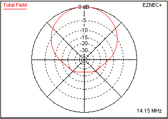
1. How does it work?
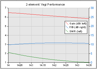
2. Yagi performance
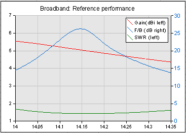
3. Broadband Hexbeam performance
4. Reflector

5. Driver

6. End Spacing


7. Wire gauge

Broadband Hexbeam - Reflector experiments
1. "Fatter" Reflector


 Before assembling a complete beam, I investigated the effect of a second wire on the impedance of a "W" dipole. The results are shown in the chart on the right and were encouraging. The key characteristic that determines the bandwidth is how quickly the Reactance changes with frequency. You can see that the addition of the second wire has had no effect on the Resistance of the dipole, but it has reduced the rate of change of Reactance quite significantly.
 Encouraged by these results I constructed a complete 10m beam with a 2-wire Reflector. The wires were joined together at the centre post terminal and at the tip of the Reflector; they were spaced by 2" at the "knee". The chart on the right shows the results compared to a beam with a single-wire Reflector.
Reflector Resonant frequency +12/-12 Ohm Bandwidth (KHz) Single wire reference 28,440 KHz 460 KHz RG174 coax -107 KHz 500 KHz 2-wire a=2.5" b=0.5" -680 KHz 571 KHz 300 Ohm slotted ribbon -265 KHz 576 KHz 450 Ohm "window" -440 KHz 600 KHz 2-wire a=1" b=1" -110 KHz 600 KHz 2-wire a=2" b=1" +193 KHz 622 KHz 2-wire a=1.5" b=3"" +626 KHz 672 KHz 2-wire a=2" b=1.5" +460 KHz 711 KHz 2-wire a=0" b=4" +710 KHz 720 KHz 2. Modified Reflector shape
 The major contributor to the HexBeam's high Q is its low Radiation Resistance (about 22 Ohms). This is caused by the current cancellation that occurs where the inner halves of the dipole elements come together at an acute angle at the Centre Post. If this part of the Hexbeam geometry can be avoided, the radiation Resistance will increase and the Q will drop.
 The chart on the right compares the measured performance of a Hybrid shape Hexbeam compared with the Classic shape. In both cases the Reflector was constructed of #16 bare copper wire; but in the case of the Hybrid the Reflector had to be shortened by 1" in order to get the tuning in-band. The "cross-connect" on the Hybrid design was positioned at a point on the support spreaders 20" out from the Centre Post, and the Driver/Reflector tip spacing was 10.5"
 Of course there is no reason why these two bandwidth extension approaches - "fatter" elements and Hybrid shape - should not be combined. Consequently I constructed a total of 11 arrays using various "fatter" Reflector wire types in Hybrid and Classic shapes. The photos on the right show a couple of examples: the first has a Reflector of RG58 coax in the hybrid shape; the second has a Reflector of 450 Ohm window in the hybrid shape and a Driver of 300 Ohm window in the classic shape.
 Each array was tested at a height of 20' for its F/B performance. The bar chart summarises the results in order of increasing bandwidth.There are no surprises here. The fatter the wire the better the bandwidth, and the Hybrid shape outperforms the Classic shape for each wire type. Some of the arrangements are more practical than others: the 2-wire Classic design delivers good performance, but its tuning is quite unpredictable; the Hybrid shape using 450 Ohm window does best of all, but construction is more difficult with this type of wire.
Broadband Hexbeam - Photographs
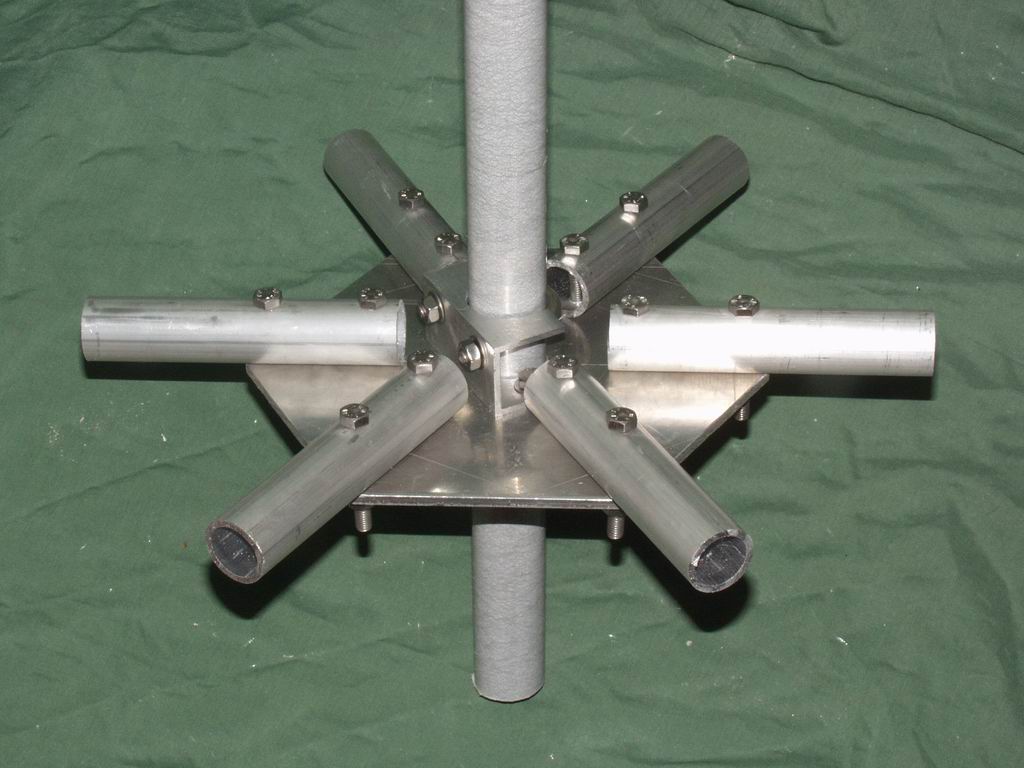 This is the all-important hub. The 1/4" thick aluminium baseplate attaches to a fibreglass Centre Post using 2 short sections of aluminium channel and U-bolts, one above and one below the plate. The spreaders slot into the aluminium tubing which is bolted to the baseplate; this method allowed the spreaders to be replaced easily when I was investigating how best to achieve the increased size needed for the new design. You can find detailed dimensional information in the following PDF files:
Centre-post support bracket
Spreader support tubes
Baseplate assembly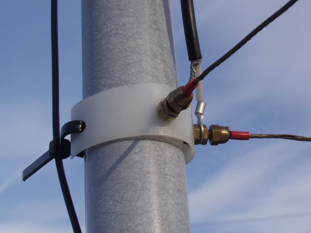 This is the arrangement I used for the Centre Post connections. Brass "dome nuts" soldered to the end of the wire elements are screwed onto 4mm brass bolts. The bolts pass through a piece of "curved plastic" cut from a used sealant container. The plastic is secured to the Centre Post by a tie-wrap; this arrangement allowed me to slide the connections up and down the Post to accomodate different wire element lengths.
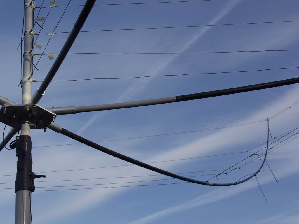 The spreaders used were cheap fibreglass "crappie poles" left over from an earlier project. The increased spreader length required for the broadband design was achieved by combining 5 sections from two 4m poles; here, you can find details on how I assembled the spreaders and the arrangement I used at the spreader tips. My final spreader lengths were 135", held out 4" from the Centre Post by the Baseplate tubing, and this provided the 130" horizontal radius required for the top 20m elements. Using other materials for the spreaders will likely require slightly different lengths because the "bow" will be different.
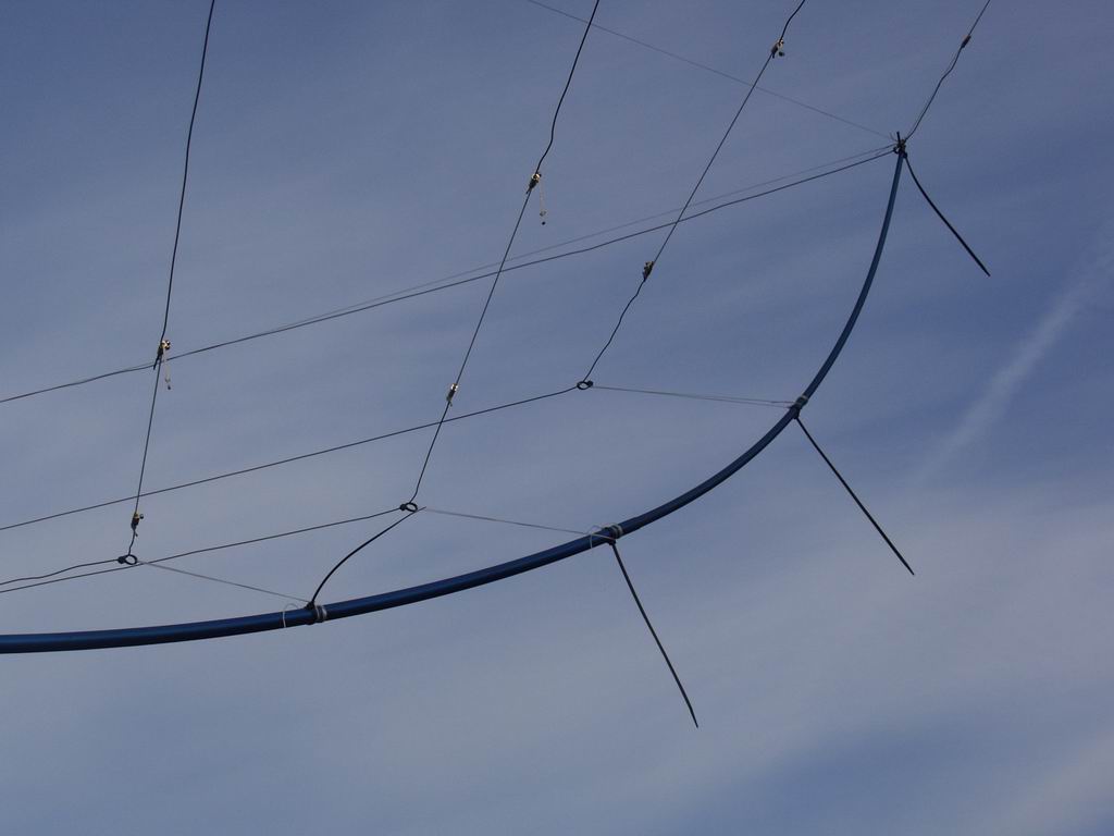 These are the temporary fixings used to attach the wire elements to the spreaders. The use of tie wraps enables the attachment points to be slid along the spreaders easily. The extension cords on the 17m, 15m and 12m wires in the photo provide fixings when the height of these elements in the support structure was such that they did not reach to the spreaders.
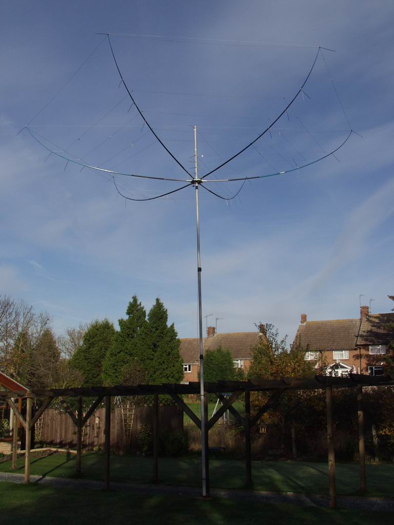
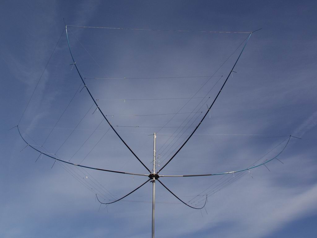 Here you can see the fibreglass telescopic mast and the final array at the test height of 20ft. The revised shape of the Reflectors and the extensions to the spreaders can be clearly seen.
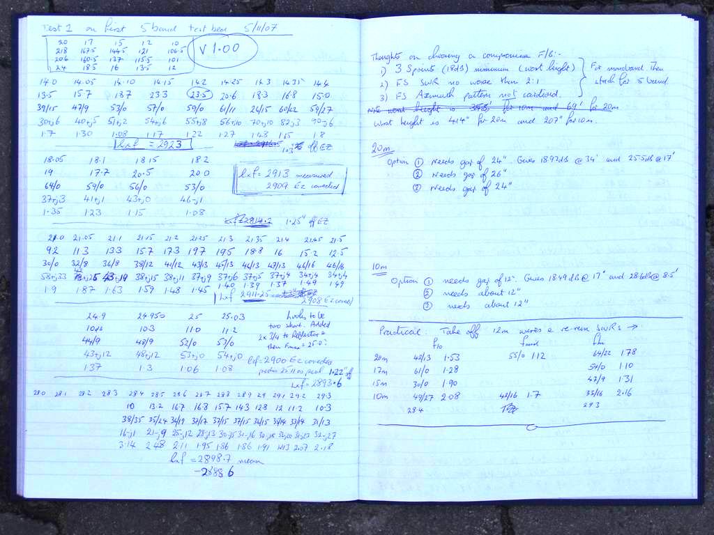 And finally, this is what it was all about ....... a sample of the 1000+ measurements in my lab notebook which involved me walking 50Km between the two ends of the test range!
Monday, June 20, 2011
Understanding the Hexbeam
Subscribe to:
Post Comments (Atom)
No comments:
Post a Comment