| Simple Dipole |
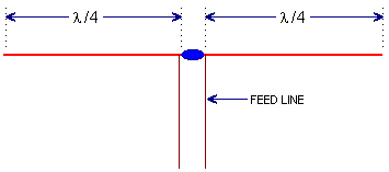
Let's start with a very simple antenna, but one that is misunderstood in a lot of ways. The half wave dipole. The half wave dipole in free space is a practical antenna with a feed point impedance of 72 ohms. The impedance can vary (R/L) depending on the height above ground, type of wire used, objects in the near field, etc. As its name implies, the antenna is 1/2 wavelength long, divided into (2) quarter wave sections.. In most applications the wire(s) are configured between (2) fixed points so the antenna looks like figure 1.
A half wave dipole in free space has a length calculated by 468 being divided by the frequency in megahertz (MHz). So let's suppose we are calculating for 7.1 megahertz, take 468, and divide it by 7.1, and you get 65.915492. Ok. I think we can round that to 66 feet. BUT WAIT. That's the ideal length. Add a about 6 inches to each end of the wire, then you can "tune" the antenna dead on the frequency by trimming back the wire as needed. (see the page on attaching to insulators). In my 40+ years of playing with an antenna like this I have yet to calculate one that has matched on the first try. I always find that I have to add or subtract about 4 inches from the calculated length, so make your wires long, then cut them back to where they need to be. Horizontal Dipole
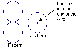
However, if we're in the tree where one area off the antenna is attached, looking at the end of the wire, you see it comes off the wire in all directions. This can work to your advantage. Let's say you live in Michigan, and have a buddy in Kentucky. You want to push as much signal south to him as possible. When you install your antenna you would suspend it between two supports, one to the east, and the other to the west. That way your signal would go north and south. Or, suppose you're live in Denver, and want to maximize your signal east and west. Put the antenna up with one end attached to the north, and the other end at the south. Vertical Dipole
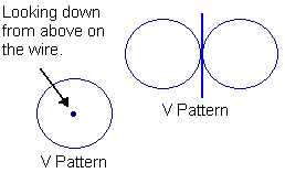
As you see in figure 3, if we were up in our balloon, looking down on the antenna, the RF would go off in all directions across the earth. This is usually referred to in most discussions as an omni-directional mode. This is favorable in most situations where you don't want to favor one direction or another. But instead of looking down on the antenna, we're standing on the ground looking at the antenna you can see that the RF comes off the antenna in that figure eight pattern, which maximizes signals to the horizon, and doesn't waste signal into the sky above. The biggest problem with a dipole in the vertical pattern mode is finding something up high to support the antenna's end. So most of the time you see 1/2 wave horizontal dipoles held up at each end by a tree, two towers, or between a house and a tree in the backyard. Transmission Line Since the antenna has an impedance of 72 ohms, you need to match it to the transmission line. There are many methods, from baluns, to coax wound around a form, or a straight line feed. A straight line feed is a piece of 72 ohm coax, cut to a specific length, feeding the antenna. This assumes proper power distribution as well as low VSWR to the transmitter. Below you will find a chart with some approximate lengths for both .66 velocity line, and .81 velocity line.
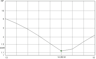
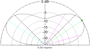
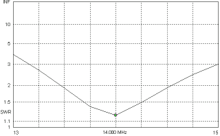
Impedance in Placement Remember how I mentioned that distance from ground and other factors can weigh on our antenna's impedance? Let's take a quick look at it. Below is a typical horizontal dipole VSWR return on an antenna designed for 14.000 megahertz. Each end of the dipole is tied up 30 feet above ground. This antenna gives us a 1.17:1.00 match at 14.250 megahertz. Best impedance is 83.26 -j9.301 which is not too shabby. Note the radiation pattern of the antenna in the plot below the VSWR graph. Note that we have a 6.83 dBi gain on the main lobe with an elevation of 34 degrees. This is real good for 20 meter ham applications.
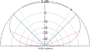
So let's lower this antenna, so it's only 20 feet off the ground. The first thing we note is that the best match has shifted down to 14.000 megahertz where it's 1.21:1.00. At our original frequency of 14.250 megahertz it's now 1.49:1.00. At 14.000 megahertz we have now assumed an impedance of 91.02+j.970. While these figures are certainly not a killer, note what happened to our radiation pattern! The best gain we can now get off this dipole is 54 degrees up off the horizon, which is awful high to expect a good ionospheric hop. For this reason, lowering the antenna actually cause a loss in performance.
This is why I always recommend that you cut your wires longer than necessary and trim them back. And keep in mind that height above ground is important as well. For 20 meters, 30 feet above ground is ideal. For 40 meters, double the distance. For 10 meters, 15 to 20 feet above ground should work well. If you are constructing a vertical dipole, then the one end can be literally 6" above ground (as long as it's insulated from ground), and the other end of the wire is straight up by a 1/2 wavelength, and fed in the center. Thus ends simple half wave dipole theory. |

No comments:
Post a Comment