
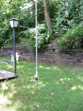
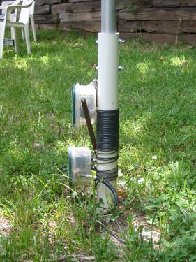
The tubes were cleaned with paint thinner, sanded to fit well, and then lubricated with LPS. The bottom mast section is bolted to a 2 foot piece of PCV tubing, used as a base insulator and coil form. The antenna sits on a Radio Shack stainless ground mount.
The top of each tube was split with a hacksaw, then cleaned with a knife and sandpaper, then the sections are held in place with stainless steel hose clamps.
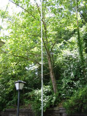
This antenna was guyed using black nylon tent cord. Before final knots were tied, the antenna was tuned to resonance at 4ØØØ khz and then the bottom stainless steel hose clamp was used to set the position. Resonance length is somewhere near 6Ø feet, it looks like it would be a job to measure the exact length.
I had lots of excess tubing to play with from 6 pieces of 12 foot tubing. I wanted at least a foot overlap inside each section.
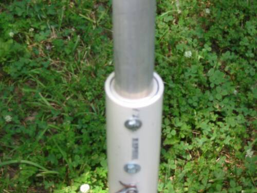
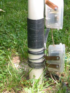
To strengthen the insulator, and increase the coil form size, the 2 inch PVC was inserted inside of a 2-1/2 inch, 2-1/2 foot long piece of PVC tubing. There is a slight amount of slop between the PVC tubes. To correct this a layer or 2 of black electrical tape did nicely. The antenna is secured with 2 1/4-2Ø stainless nuts and bolts.
The electrical connection is made with a separate stainless steel 1Ø-38 nut and bolt stud mounted through the PVC and antenna tubes. The loading and matching coil connections are also mounted to SS 1Ø-32 nut and bolts inserted below the antenna mast.
The turns for matching and loading may vary somewhat from one installation to another, but my settings should be close. As with any antenna, fine tuning may be required.
If you are not interested in using this antenna on 16Ø meters, You won't need the relays or loading coils, only a 7 turn matching coil, and then tune the length of the antenna to your favorite frequency on 8Ø meters.
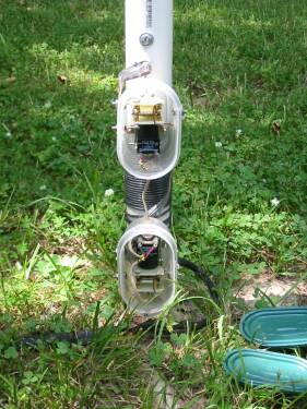
The switching relays are mounted in a tupperware dish. Stainless 1Ø-32 screws and nuts are used as terminal lugs. The connections to the relay are made with number 12 wire, brought through holes in the case and connected to the terminals on the outside, so the screws are not part of the circuit. After the relay boxes are installed I suggest applying clear silicone glue to all holes where wires exit. So far I haven't found any moisture build up inside.
If you can find something heaver than a tupperware box, I strongly suggest it. These first installations only lasted a year before the plastic started cracking.
The model is Magnacraft W158HVX-1. If a 12 volt relay could be found there would be no need for building a separate 24 volt supply.
The Antenna feed point is connected to the upper loading relay center arm. When both relays are in the normally closed position, (no power supplied) the antenna is in the 8Ø meter position. The upper relay closed contact is connected to a tap at 11 turns from ground (8Ø meter loading), and the lower relay closed contact is connected to a tap 7 turns from ground (8Ø meter matching).
With 24 vdc applied to the relays, the antenna switches to the 16Ø meter band. The upper relay open contact is connected to a tap at 46 turns from ground (16Ø meter loading), and the lower relay open contact is connected to a tap 8 turns from ground (16Ø meter matching). The antenna loading/matching coils supply a DC ground on the antenna for static and lightning discharge.
I put 4 sets of guys on my antenna, one on each section, top free standing. I got fancy, and cut 5 each guy brackets from a piece of 1/8 inch thick alluminum rack panel. I made them square and cut a center hole in each to nicely fit each expanding mast section.
Then I drilled 4 each 1/4 inch holes in each corner for the 1/8 inch Nylon guy twine. You could also tie the guys around a hose clamp for each section, but you would have to jockey with this while raising the antenna. I had all guys in place when I started raising the sections.
You must raise the antenna on a calm day, very slowly, keeping the antenna straight as possible. It will free stand at 6Ø feet if you tie the bottom steel guys secure, and tight, and have the antenna insulator sitting around a radio shack mast support or some sort of ground stake to secure the antenna base from moving sideways.
I left about 5 inches of the metal steak sticking out of the ground, no more though as it will interfere with the coils. After raising the sections, lightly tie off each guy by itself, they will be permanently secured after tuning.
Finally, remove the steel guy wire in order to tune the antenna. Be sure to have help when raising this antenna. Although I did it by myself, I have had a lot of experience with slip up masts. What ever you do-
Disable any other connections to the coil, and install a jumper wire from the antenna feed to the 7 turn tap. You should now have only the 7 turn matching coil and the 6Ø foot antenna in the circuit.
Tune your radio close to 4 mhz, and then fine tune your antenna for the lowest VSWR by adjusting the second antenna section up and down inside the first.
You will have to do this in small steps, loosing all but the bottom guys slightly for each test. When the antenna is tuned, complete vertical alignment of the antenna, and secure the nylon guys.
Next, fine adjustment is done first by tuning your transmitter to your favorite 8Ø meter frequency, and adjusting the amount of turns, and spacing of them, on the 3 turn coil for 8Ø meters.
Next, fine adjust the 35 turn coil for 16Ø meters on your favorite frequency.
You must tune the 8Ø meter coil first as it is part of the 16Ø meter coil.
I have been getting good reports from as far as Florida on 16Ø meters, and without a tuner, I can spread most of the phone band on 8Ø meters. I can spread 1ØØ Khz on 16Ø meters. With the tuner in my Yaesu FT92Ø, I can spread the whole band on 8Ø or 16Ø meters.
I tried the LDG remote tuner. It would not work at all. It would only tune a few frequencies. I sold it and purchased a SGC-23Ø tuner. It cost twice as much, but it tunes this antenna to all the bands just fine.
There is more information about the SGC-23Ø upgrade in my 8Ø/16Ø upgraded to 1Ø/16Ø meter antenna section.
No comments:
Post a Comment