The Concept
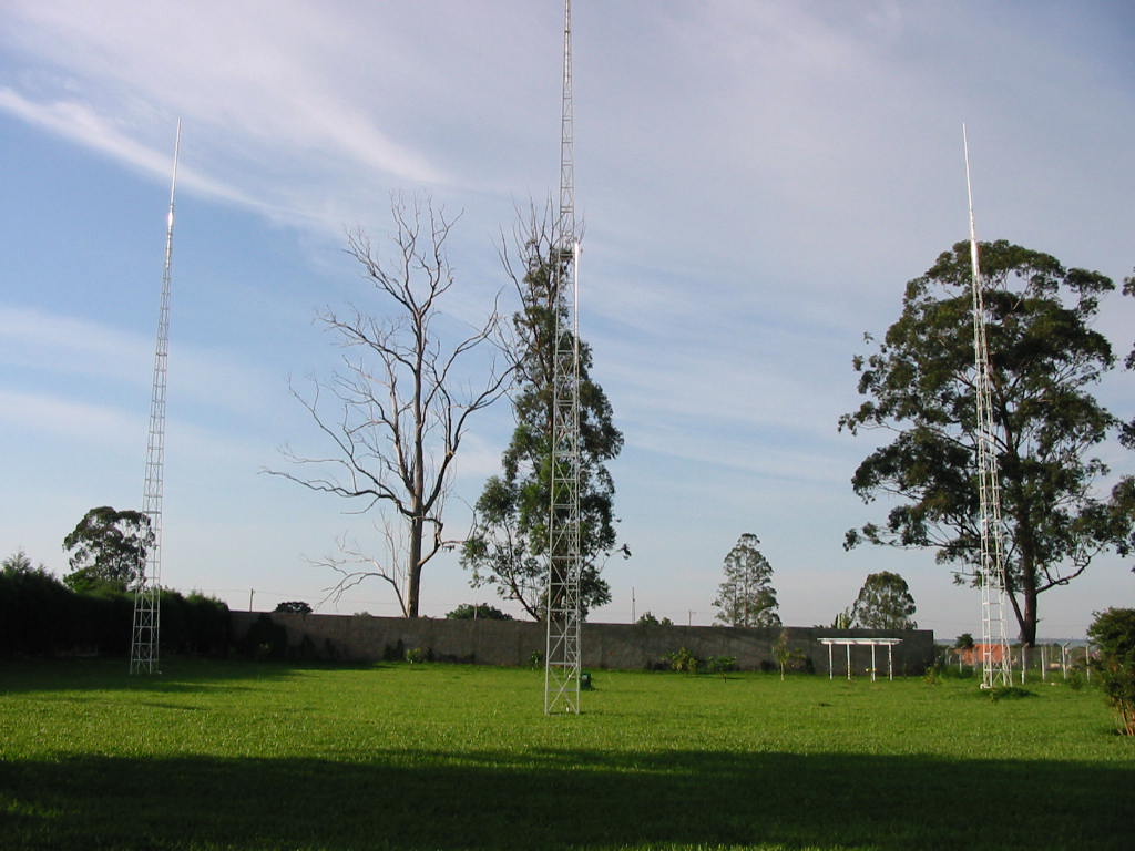
 | The antenna is composed by a set of four verticals, 1/4 wavelength height, considering the operation frequency, e.g. 3,650 kHz, positioned at the vertices of a square whose side is also calculated from the same frequency, which means 67 ft and 5 inches. The antennas are phased by feeding them up with coaxial cables whose lengths are calculated by the physical length at the operation frequency multiplied by its speed factor. The antennas are switched by a Hybrid Phasing Coupler developed by Comtek Systems Inc, which is a phase box where are stored an electronic circuit, relays among other components. Once the antennas are properly phased the transmitted signal by a specific antenna will be toward the square diagonal directional, turning the other 3 ones as parasites. Towers were chosen as vertical elements instead of the aluminum tubes since their large base have made the antenna broad band resulting in better values for SWR as well on both sides of the band, e.g. the CW and phone DX windows, at 3.510 and 3.790 MHz. The tower guys were suppressed in order to avoid interaction between the towers and the others antennas on the site as well. Besides of that the XYL, PY2YL, demanded not to use it due to esthetical reasons. She said so. |
|---|
Assuming that one side of the square is paralleled to the equator line the diagonals are pointing to Europe, Africa, Oceania and USA. The towers are fed with equal currents, so, when the European tower is switched on it will be being fed at -90 degrees, the side towers, e.g. the Africa and USA towers will be being fed at zero degree, while the Oceania tower will be being fed at +90 degrees. The signal direction will be toward the diagonal from the back to the front tower, it means, from +90 to -90 degrees, in this case the maximum gain will be toward the Europe. Obviously using a relay box the signal can be easily switched to anyone of the square vertices doing a roughly directional antenna. The -3 dB irradiation lobe is around 60 degrees and the take off angle is close to 17 degree.
There are 3 factors that directly do contribute to a vertical antenna performance:
- Gain;
- Irradiation angle;
- Pseudo-Brewester angle.
These 3 factors altogether are directly related to the soil electrical conductivity and the number of radials used as well. The ideal location is a very wet terrain very close to the sea, or, if this is not possible, the use of at least 240 radials two-wave length (135 ft) per tower will do the same. In this particular installation, due to the lot dimensions restriction, this solution was not possible. Adopting the simulations made by Devoldere for similar electrical characteristics soil using the NEC - Numerical Eletromagnetic Code software the best compromise solution was chosen. The site antenna soil may be classified as medium soil accordingly to Lewallen assuming K = 13 and conductivity = 5.0 mS/m (miliSiemens per meter). These values do recommend 60 radials per tower 67 long each. | 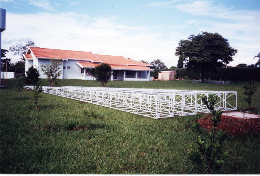 |
|---|
The antenna simulation results showed the following:
- Gain = 5.2 dB;
- Take off angle = 17 degrees;
- Pseudo-Brewester angle = 8 degrees;
- Front/back ratio = 20 dB.
These values are quite significant for a low band antenna. To learn more about the Pseudo-Brewester angle, please refer to the Low Band DXing book by John Delvodere published by the ARRL.
Dimensions
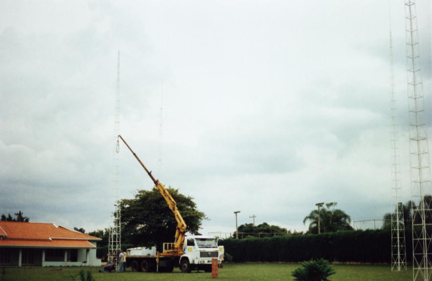 |
Tower height is 56´ 5” plus a aluminum pipe 2” OD which does act as a fine tuning element allowing to find out the exactly system length for the design frequency at 3.650 MHz. The design frequency resonant was found at 66’ 7” height. It is important to keep in mind that each tower top must be at the same level. Each tower has a prismatic shape with a square 28” basis and 5” side at the top. The towers were positioned at the vertices of a 67’ 5” side square and 95’ 4” diagonal. The terrain was carefully leveled in order to assure that the towers top level were the same. |
|---|
The towers are connected by 50 ohms coaxial cable to the Hybrid Phasing Coupler, which is located at the diagonals crossing point that is connected to the linear amplifier inside the shack 165 feet away. The coaxial length from each tower to the HPC is quite critical and must be cut using a grid deep meter otherwise the antenna will not be properly phased therefore will not work as expected. It is important to notice that the distance between each tower and the HPC does represent an interesting problem: the coaxial physical length is the product of the velocity factor by the electrical length. Using a coaxial with polyethylene as dielectric medium the physical length will be 67.42 * 0.66 = 44.49 feet. As stated above the diagonal length is 95’ 4” or 47’ 10” between each tower and the HPC. This is clearly insufficient to reach the tower. The only way to solve this is to use another coaxial type as FOAM or CATV whose velocity factors are 0.78 and 0.81. Accordingly to the ground simulations 60 radials per tower were laid, each radial 67 feet long totalizing 16,080 feet of 14 AWG copper wires. The total area occupied is 34,950 square feet. | 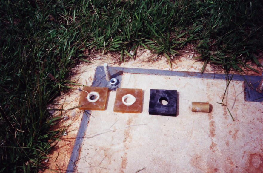 |
|---|
Construction
The towers were carefully designed to achieve the following goals:
- Impedance as close as possible to 50 Ohms;
- Reduced wind resistance;
- Lowest height/base ratio.
 | These last two parameters associated made the towers cost being affordable, helping to reduce the foundation cost as well. The tower structural analysis showed that the bend strengths due to self weight and wind load were small enough to point to a conventional foundation consisted in a block supported by a single 8” diameter concrete pile 10 feet long. The concrete block base has a steel frame structure, cube shaped 32" side, using “L” shape 1.2” by 1.2” with 1/8” thick; each side of the cube is crossed with a 1/2” diameter steel bar. This frame is anchored to a single bored pile located at the block center. The bored pile is 8” diameter 10 feet long embedded with a single 7/8” diameter steel bar. The bored pile contributes to lower the gravity center, besides helping to resist the strengths caused by the tower bend in the block. The concrete used is able to resist compression strength up to 18 MPa. The block is one inch larger than the steel frame to avoid it being attacked by the soil humidity. |
|---|
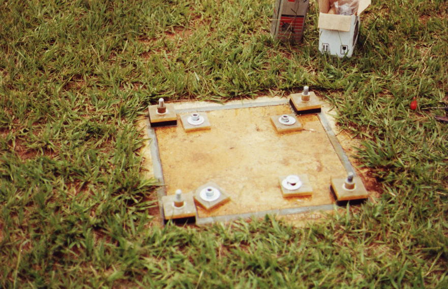
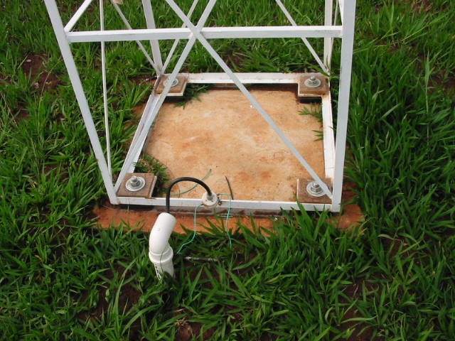
The antenna design demanded that all the four towers were perfectly insulated from the ground. The solution adopted was to use of fiberglass cylinder and plates. The cylinder is 1/2" internal diameter and 1 1/2" OD. The screw that emerges from the concrete base fits perfectly inside the cylinder avoiding any physical contact with the tower foot. By its turn the foot tower stays enclosed by 2 fiberglass plates. Each plate is 1 1/2" OD drilled in its center where the cylinder goes in. Each plate is squared shape of 4” side and 1/2" thick. The plate located over the tower foot does support the washer and nut. The plates and the tower foot are placed over a neoprene squared plate of 4” side and 7/8” thick that is by its turn placed over the concrete block. Of course the neoprene plate has also 1 1/2" hole to allow the block screw to pass. This system was conceived in order to overcome the mechanical strengths due to winds and vibrations which are absorbed by the neoprene, and the RF is absorbed by the fiberglass set. The neoprene plates are quite expensive so its use was possible by a special courtesy of the Stela - Sociedade Tecnica de Elastomeros that graciously gave 16 pieces. Laboratory tests showed that the neoprene is not capable to handle power over 1,500 Volts so the neoprene alone could not be used to absorb both electrical and mechanical tensions.
|  |
|---|
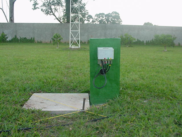 | The radials are copper wire 14 AWG 65 feet long positioned at every 6 azimuthal degrees. In order to have all the 240 radials well positioned over the ground a simple design was generated using the script AutoCad tool. A copper tube 1/4" OD in a circle shape 18” radius was placed surrounding the tower. One tip of the each radial was soldered at that ring and the other one was fixed to the ground using a large nail making the radials well suited. A 165 feet trench was excavated from the shack to the towers diagonal cross point. A 4” PVC tube was laid to run the coaxial from the station to the Hybrid Phasing Coupler box which is placed on masonry pile 2 feet height. The PCH is tied to this small pile facing north to minimize the weather effects. The coaxial cables from the PCH runs inside the pile to a buried concrete box where they are distributed to each tower through PVC tubes 2” OD. |
|---|
Performance
At the very first measurement the antenna did show absurd SWR values in the NW to SW direction. A careful inspection in the whole system pointed out to an un-plugged connector in the phase box, that once fixed showed SWR following values:
| QRG | 3.500 | 3.650 | 3.800 |
| SWR | 1:1,7 | 1:1,2 | 1:1,6 |
Please click here for the measurement complete report.
The antenna does work very well transmitting and receiving, allowing assuming that the performance is very close to the design values. Quite often weak signals can be heard when others stations around cannot copy a single peep. It can be said that the antenna, when receiving, has approximately a two-wave lengths beverage performance. One night when propagation was just above marginal conditions, the SM7EHU station operated by Per did show up also using a four square. The QSO did look as a 20 meters chat with the noisy level around S6. The SM7EHU signal was close to 10 dB over S9. Some directive signal tests were done during the QSO. When the antenna was beaming to the USA, e.g. SE-NW, Per couldn’t copy, the signal dropped inside the noisy, S7 on his side. When the antenna was switched to Africa, e.g. NW-SE, the same happened. Per guessed the front/side ratio as 3 S units, which is quite close to the design expectation. | 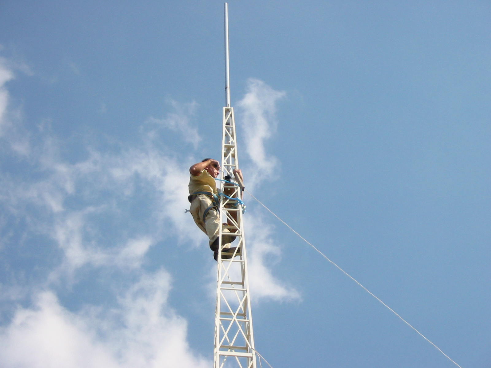 |
|---|
Conclusion
The pleasure to attend the 80 meters band without those so peculiar horrible crashes and clunks does worth all the planning, construction and time expended on it.
Credits
- Structural analysis: Eng Arthur Jose Magalhaes de Assis Bastos
- Foundation: Eng Cesar Augusto de Camargo Rodrigues
- Civil Works: MSG Engineering Ltd
Bibliography
- "A Switchable Four Element 80-Meter Phased Array", by Fred Collins, W1HKK/W1CF, March 1965 QST.
- "Antennas and Techniques for Low-Band DXing", by John Devoldere, ON4UN.
- "The ARRL Antenna Book" by R Dean Straw, N6BV, published by ARRL.



No comments:
Post a Comment