
S.W.R. (vswr)
The SWR of the antenna tells us how much energy from the transceiver is radiated in space (forwarded), shortened FWD these 3 letters is what you might see on the SWR meter. It tells us also how much energy is radiated back (reflected) shortened REF, also these letters can be found on the SWR meter
How those two things Ref and Fwd are holding-up to each other is what we call the : SWR.
1:1 tells us all power (energy) which is sent is gone out of the antenna and nothing has returned
What SWR does NOT tell us is how the antenna her features like GAIN are holding up.
SWR does not tell us how the antenna preforms it can be that where your SWR is 1.1:5 the antenna is at its best looking at gain or front to back!
It has no use to bring the SWR down as low as possible.
Up front if you want to measure your true SWR. You will need to do that at the Antenna side and not at the transceiver side.
The radio has an Impedance of 50 ohms the coax cable we use is also 50 ohms and when the antenna is also 50 ohms you would see an S.W.R of 1,1. However if there is a miss match, there will be what we call running waves on your coax cable. these will influence the SWR so you cant read "true" SWR figures at your radio location.
The story you heard about cable length,: that exact length figures are important it probably originates from here: When a coax cable has an electrical length of a half wave or a multiply of this it shows us exactly the same as it does on the other side of this coax cable. So it is possible to read the SWR values below at the TRX, the cable just has to be an electrical half wave long..(calculate half- wavelengths with the velocity factor of the coax cable.)
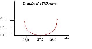
Above we see an example of an SWR curve. This could be an example of the SWR of your antenna. You see the boundaries are at 27 and 28 mhz there the SWR rises above 2,0:1.
Too long, too short?
Say your SWR measurements came out with an SWR from 1,8:1 at 27,555 and 2,0:1 at 27,600 this means your antenna is too long
Simple said if the SWR is higher, higher in frequencies the antenna is to long
if the SWR is higher, lower in frequency the antenna is to short
This is easy to understand :
300 / frequency in Mhz was the wavelength
300 / 27,6 = 10,87 meters, 300 / 27,5 = 10,9 meters so the wavelength is getting longer lower in frequency we already knew that.
If my SWR is better lower in frequency this will mean then my antenna is too long! simple as that.
How much loss do I have with SWR?
What SWR percent power out SWR percent power out SWR percent power out.
SWR | Percent power out | SWR | Percent power out | SWR | Percent power out |
1.0:1 | 100% | 1.4:1 | 97,2% | 1.8:1 | 92% |
1.1:1 | 99,8% | 1.5:1 | 96% | 1.9: | 90,5% |
1.2:1 | 99% | 1.6:1 | 94,7% | 2.0:1 | 89% |
1.3:1 | 98,3% | 1.7:1 | 93% | 3.0:1 | 75% |
The conclusion which can be made is as follows: There is no one which can see or hear the difference in signal strength between 1.0:1 and 1.5:1 NO ONE.
The optimistic thing is, that gain and front to back, never are high where the SWR is low.
So compromising in SWR is something to keep in mind.
My SWR is around 1.5...1.6:1 and I am not gone change anything.
BANDWIDTH
One of the last interesting factors of a antenna. The Band with of an antenna is where the SWR remains below the 2,0:1 figures.
Since SWR was in a parabolic shape it has two frequencies where swr reaches these values (see SWR diagram above) When a yagi is designed, you have several options you could make the bandwidth wide (1 mhz or greater) but the gain, F/B, will be down although this is not exceptional much, numbers as 1dB are not uncommon if compared to a yagi with a small bandwidth.
These small band yagi's are thus high Gain yagi's but only over say 300 Khz.
There are ways to improve the Bandwidth of a yagi you could make the element thickness thicker (of the radiating element) this will give you say 100 khz extra it will not be a Mhz.
Other ways are to use a Folded dipole as radiating element. With a folded dipole comes a higher impedance but you could lower it down to 50ohms with other matching technics as normally used.
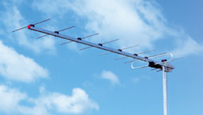
A folded dipole is often used in the VHF , UHF spectrum above you can see a 9 elements Tonna yagi for 430 Mhz with a folded dipole for the broad bandwidth.
There are beams with a standard wide bandwidth examples of these are the Logcell yagi (this on is capable of giving you a beam with between 26 Mhz and 28 Mhz. But the overall gain of a logcell is sadly not 11dBI as you might see in adds but more in the order of 6 dB which is equivalent to a 3 elements yagi.
No comments:
Post a Comment