Coax Cable:
![]()
![]()
Coax Cable does only need to do two things:
1) To take the received signal from the antenna towards the receiver.
2) To bring the transmitted signal from the transmitter towards the antenna is through a coax cable.
These are the only purposes of the cable.
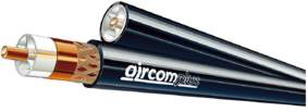
Most commonly used are RG-58, RG-213, Aircomm, Aircell.
There are bigger types like 3/8 or 7/8 hard line but this will cost and perhaps it is of no use to use these types simply because the length between your antenna and transceiver is short enough to there is hardly any loss!
You might start thinking about those when you need more then 50 meters.
(At 11 meters I could not see the difference between 3/8 and Aircomm Plus over 30 meters only in my wallet!)
Very lucky we should be, that there are no big misunderstandings about cable. It is as simple as:
Buy a line with the lowest cable attenuation
Do not make the cable any longer then necessary
The first highly depends on the money you would like to spent on cable.
Overall can be said that: the higher the cost the better the loss.
In extension of the second there are misinterpretations by some, regarding "the ideal length".
As said, you only have to keep one thing in mind, keep it as short as possible.
WHAT LENGTH?
As mentioned the best length is the shortest, in this way the loss due to the cable is the lowest.
There can be one advantage by extending the length of the cable:.
A HALF WAVE coax cable or ANY multiple (1, 1½, 2 wavelength) length of this will show you: "exactly the same input resistance at both ends of cable". In normal words:
You can measure the exact SWR from the antenna with these lengths of coax cable.
If your antenna is truly 1:1 it doesn't matter, each SWR measurement anywhere on the line and you will find 1:1.
Only when your SWR isn't 1:1 but higher your measurements will change according to length, this is when it can come in handy to keep the line a half wave long (or any multiple).
And there are always SPECIAL CASES:
There are antennas which depend on the coax cable for the to produce "the ground", some mobile antennas and very small bases verticals could need this. Read the instructions before cutting them. Any full size antenna does not have this problem! And just make sure you do not use types mentioned before unless there is no way to overcome this.
When you want to combine antennas together(stacking) other features come in, read the chapter Stacking.
OPTIMAL LENGTH BETWEEN LINEAR / ANTENNA / TRANCEIVER ??
There are stories about the length between an amplifier and the antenna/ transceiver. The above goes for this as well.
Just keep it as short as possible, there is no benefit to make it anything else
CABEL IMPEDANCE, Other figures
The cable has other characteristics: it has an impedance, power handling capability.
Most commonly used is 50 ohm's cable.
Sometimes it could be useful to have 75 ohms (for stacking). Another variety is: 300 ohms, this is what we call open line.
This was/is still in use for simple wire antenna's often multi band antennas.
We will stick to the 50ohms, that's what we needed Flexible/ able to lay in corners etc!
The impedance (50 ohms) of the cable is produced by it thickness, the distance between the two conductors and the material between those conductors.
With the knowledge of this you can now make up your own mind, Is it wise to bend coax cable in a tight curve?
No you just might changes the distance between the two conductors!
Do not bend the cable in straight curves (let the cable take the turn it wants! no sharper, this also counts for storage)
When welded the cable, make sure there isn't a possibility for water to enter the cable.(vulcanized tape)
POWER HANDLING CAPABILTIES:
The thickness of the inner cable is responsible for the power handling capacities. The thicker the better.
RG58 witch is one of the thinnest cable can handel up to about 300..400 watts .
Any thicker size cable can handle 1 kw easy
( RG 213 about 1800 watts, Aircell 7 about 2,5 KW at 11 meters and Aircom up to 5 KW.)
LOSS: with 100 meter length

You can calculate easy with these numbers for example with only 20 meter cable using RG-58 we come to
6,6 / 5 = 1,32 dB loss (100 meters RG 58 was 6,6 dB loss we want the loss at 20 meters: 100/20=5 ..... 6,6/5= 1,32dB)
So when we stay below 50 meters Aircom Plus is good enough we only reach a loss of 0,75 dB then. (not included the connectors etc.)
 Aircell 7
  Aircom plus
CONNECTORS:
PL 259 is most commonly used type. although this type is not 50 ohms, I know my mind is a bit extra-careful but I only use N-connectors these are 50 ohms so any loss which just might exist with PL 259 connectors is reduced. Honestly I have to say I never noticed any difference on 11 meters between those connectors.
Use only the amount of connectors you need and that is 2 !
Once's tested the S.W.R this will probably be the same next time. How nice it is to see those needles going up, but again this is loss ...extra connectors, S.W.R meter etc.
COAX AND VELOCITY FACTOR
The shielding and the core of a coax form a capacitor. Through the use of insulation material, the value of the capacitor is bigger then it would be in air, and this has the effect of slowing down the signal. This can be of great importance in some applications, although for many purposes it does not needed this information ;-)
Velocity factor
The speed at which the signal travels is normally given the abbreviation VF and this is the fraction of the speed at which the signal travels when compared to a signal traveling in free space. So VF for a signal traveling at the speed of light would be 1.0, and for one traveling at half the speed of light it would be 0.5.
The velocity factor of the coax cable is found by VF = 1 / SQRT (dielectric constant)
Coax cable electrical length
One important factor of a coax cable in some applications is the wavelength of the signals traveling in it. In the same way that the wavelength of a signal is the speed of light divided by the frequency for free space, the same is also true in any other medium. As the speed of the wave has been reduced, so too is the wavelength reduced by the same factor. So if the velocity factor of the coax cable is 0,66, then the wavelength is 0,66 times the wavelength in free space.
In some instances lengths of coax cable are cut to a specific length to act as an impedance transformed or a resonant circuit, then this needs to be taken into consideration when determining the required length of coax cable.
The advantage of using a coax cable with a low velocity factor is that the length of coax cable required for the resonant length is shorter than if it had a figure approaching one. For example, 1/4 lambda 75ohm coax (VF * 1/4 lambda length) for transform the impedance from 125ohm to 50ohm.
Dielectric materials
There are different types of materials that can be successfully used as dielectrics in coax cables. Each has its own dielectric constant, and as a result, coax cables that use different dielectric materials will show different velocity factors.
Coax Insulation Material | Dielectric Constant (Er) | Velocity Factor |
Polyethylene | 2,3 | 0,659 |
Foam polyethylene | 1,3 - 1,6 | 0,88 |
Solid PTFE | 2,07 | 0,695 |
Dielectric constants and velocity factors of some dielectric materials used in coax cables.
Wire Beams
When using insulated wire for a wire beam you have to change the lenght. VF of the wire is between 0,98 and 0,95.
ANTENNA TUNERS
Do not use it.
If your antenna is not resonant at the design frequency and you need an ATU to make sure the SWR stays below the wanted numbers. You have done something wrong!
There is only loss in an ATU due to extra connectors, and the inside of the ATU (coil/capacitor)
Most people use the antenna tuner directly after the transceiver, it is only logical that the SWR does not become better It is NOT an ANTENNA tuner but only a CABLE tuner!
Remember a dummy load had an SWR of 1:1,1 but was a terrible antenna the same counts for an ATU.
The ATU is the joker in our system.
DONT USE IT!
ONE EXEPTION:
There is only one way that the ATU may be used for what it is ment for.
That is with non- "conventional" types of cables and antennas. (that 300 ohm line for example).
The case here is that these impedances are way of 50 ohms.
But neither will be used by 99,9 % of us 11 meter DXers.
PS Taking a look at most antennas, you'll often find coils in them. You could look at it as an actual "fixed antenna-tuner", but this is of course not what we are speaking about.
RECEIVING PRE-AMPLIFIERS
The device, which can improve a received signal.
Works on 12 volts has an input and output connector (commonly PL259)
This for me is an un-know region at the 11 meter band.
In the new setup I will include one of the below marked pre-amps and will put down the results.
Of course,i also had once such a device available from the CB-market, only to find out the noise level was improving with great numbers perhaps when I used bad cable it could have been an improvement.
The mentioned noise level is the quality figure of the pre-amp. At higher amateur frequencies these devices do come in handy because they do make up for all the loss in cable connectors etc. (I can notice a big difference on 144 mhz and 934 mhz)
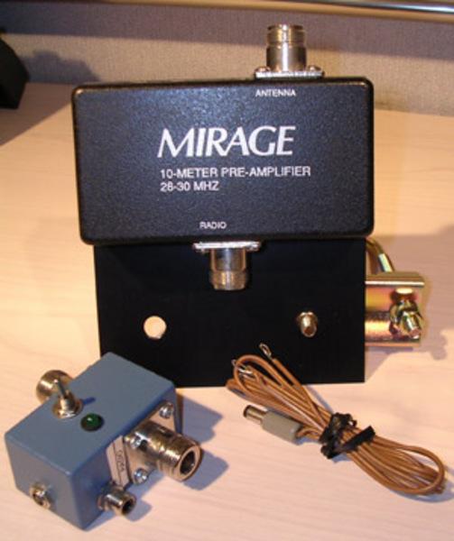
Professional pre-amplifiers like those from MIRAGE or ICE have a noise figure of < 1dB and a gain variable up to 20 dB.

The amount of power they can handle is not that high, Of course with remote switches this is a problem you can overcome.
There is only one reason why you should use a pre-amp
To make up for the loss produced by connectors and cables.
So often it is put where it should not be ....at the transceiver his location, this could help in the old-days due to bad receivers but these days the transceivers all are perfect and really do not need one.
The right location is at the bottom of the antenna, only then it might bring stations a bit clearer.
Yes almost forgot: The signal which your antenna does not pick up, can not be amplified by a pre-amp..
GAMMA MATCH
The Gamma match is the most used matching device used for yagi beams.
What it does is:
A Yagi almost never has an impedance of 50 ohms. In other chapters i told that Gain, bandwith, F/B etc. all relate to eachother these figures are never all high at one point. A well designed yagi has for that reson an impedance around 20..25 ohms.
A Gamma-match can match impedance below 50 ohms right up to that 50 ohms wich your tranceiver wants to see.
The thickness of the rod should be around 1/2 part of the radiating element, The lenght in the order of 0.05 wavelenght long.
This comesdown to
The desgribed Gamma-match is used for 11 meter Yagi's with an aluminim element thickness around 25mm !!!!!!!!
I am however convident that with slight adjustments it will work for other diameters.
For the dimensions I took the outside diamter of the radiating element (F) in the order of 2,5 CM.
F is an aluminum plate and should be about 0,5 cm thick and wide enough to hold a N-connector female or
the equivelent PL version. Preferbly in an L version so you can attach it to one of the U-bolts holding the
radiating element to the boom. The hart of the connector should be 10 cm from the hart of the radiating element
A the N- connector female or the PL version
!!! is between the two aluminium tubes B and C must be NON-electrical guiding material for example:
the “plastic” used in coax-cable.
The length of it must be a bit longer then the lenght given “G” !!!
C The long aluminum tube about 1,3 cm thick and 70 cm long.
D An aluminium plate drilled with three holes 1) the driving element
2) the tube D
3) on top a screw to hold it in place.
the holes should be from center to center 10 cm separated
E the radiating element also called driven element.
B Aluminum tube with a length of 13,5 CM diameter 1,8 CM (C and D goes into it)
By adjusting the aluminum plate left or right, you should be able to get a low SWR.
This Gamma-match can handle up to a couple KW’s.
The Dipole
PKW
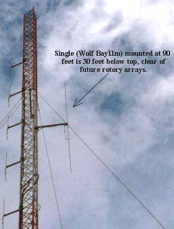
 Wolf
Wolf
This antenna is the basic. It is simple to make and cost can be nearly nothing.
Most antennas are based on a dipole, Yagi's use a dipole antenna as the radiating element, vertical half wave antennas are "end-fed" dipole antenna.
And so can mobile antennas be brought back to this principle.
A dipole antenna : developed by Heindrich Rudolph Hertz around 1886 is an antenna with a center-fed driven element for transmitting or receiving radio frequency energy. These antennas are the simplest practical antennas from a theoretical point of view. ref: wikipedia
The antenna consist out of one electrical guiding wire with a length corresponding to the frequencies.
Often this wire is made out of copper, but any electrical guiding material will be ok.
The 50 ohm feed point is in the middle of the antenna.
At that point the wire is separated and connected to a coax cable.
At the ends of the dipole there are insulators to make sure the antenna
The Dipole can be found in many different shapes, it maybe erected horizontal (it is called then a Horizontal dipole)
(as in the second picture above.)
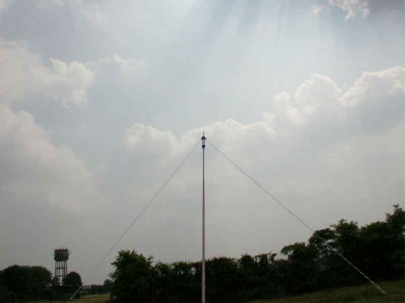
Or could be erected vertical (iow Vertical Dipole), as in the third picture above.
Another common shape is in an up side down V shape (it is called then in Inverted V antenna)
as in the first picture above.
Finally you could find it in an angle of 45 degrees (called a sloping dipole).
With the variation of each shape the patterns of the antenna changes and there for personal preferences may vary.
WHICH LENGTH ?
The first symbol is lambda, it is the sign for wavelengths.
The formula then is 299,8 divided by the F which is frequency in Mhz ) will give us the wavelength of the frequency.
Example: channel 52 (27,555) 299,8 / 27,555 = 10,88 meters
This is approximately 11 meter (that's why everybody speaks about the 11 meter band.)
WHAT DO WE NEED ?
A dipole is a halve wave antenna, the length of the dipole for 26,285mhz (my design frequency) would there for be : 5,70M.
So we need :
2 pieces of 2,85 m copper wire.
Two end insulators and one center piece.
Coax cable to connect the antenna to the transceiver.
center piece -------------------------- Electrical guiding material ------------------------------- Rope
The "professional" insulators can be bought on any ham market or ebay etc.,
you could get the through me (cost 15 euro together. mail 19SD348@planet.nl ).
But, u do not really need them.
You can make it from wood or plastic see the chapter "SKYPPER" for another idea.
A search on google might give u a hand a swell.
MAKING THE ANTENNA WORK !
All you need to do is connect the individual wires (2,85m) to the center insulator, and connect the end insulators to the other end of the wire.
Connect the coax cable to the center insulator.
Then connect the rope to the other side of the end-insulators and pull the antenna in the air.
Now you need to check the SWR with your SWR meter.
Keep in mind that SWR varies due to - height
- ground capabilities
- nearby structures
Make always sure u make the antenna a little longer then designed. .
When the SWR is the best, lower in frequency your antenna is too long.
when the SWR is the best, higher in frequency your antenna is too short.
Start extending/cutting the length on EACH side !
On the eznec file u can see that the gain is 0,0 dB.
This is correct a dipole doesn't have any gain compared to a dipole.
This antenna is a reference antenna to others when gain is expressed in dBD !.
SWR MEASUREMENTS:
Below u can see how the MINIVNA antenna analyzer responded to the antenna:
The best resonant frequency was : 26,270 mhz
The Bandwidth ( 2:1 points) of the antenna is: about 1,5 mhz !
Results:
On 02 October 2008 (sunspot minimum) stations from Italy,Spain,Balearic island,Sardinia,Cyprus, Macedonia, Bulgaria,
Corsica, Ireland were worked in a morning with only 15 watts, on 27mhz.
Now that is loads of fun with only a little money spent !

No comments:
Post a Comment