
BASIC
As always you have to know a few basic things, again YOU HAVE TO KNOW.
Without all the numbers meaning anything to you, you can not make a right decision.
So what is an antenna then?
That question came to mind and an explanation was found by going through some antenna books: The antenna had to be capable of doing a few things:
The transmitted energies by the transmitter had to be transferred into Electromagnetic waves and broadcasts away from the antenna.
For receiving the same trick must be done but then opposite. Electromagnetic waves need to be taken from the sky. Transferred in to small amount of hf energy and "decoded" by a receiver.
The one who would do this job the best, would be the best antenna.
In real life it sadly is not possible to transceiver under all angles equally.
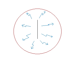
The only antenna which can receive and transmit under all angles equal is called an isotropic.
This antenna only is real in our minds it can not exist in real life, this is due to the influence of earth. You can imagine the radiation pattern of an isotropic antenna as a football in which the antenna is the center point of the ball.
This type is used quite commonly because it is the only one which radiates in all directions equal you can use it to compare antennas.
in other words:
to use it as a standard for gain.
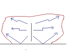
The same antenna but now in real life, we have put the earth beneath it.
These simple diagrams are fast made, but in real life it is just like this...there is no antenna which produces a nice round pattern it is quite a lot like the picture to the left.
GAIN
If you would say my car runs 10km faster everybody wants to know...it runs 10 km faster then what?
In the antenna world its the same. If you have an antenna and want to know if it works better you will have to compare it to something.
Further you will have to have an expression to tell us how much strong it actually is. In the antenna world you can imagine Gain as the following diagram:
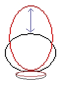
The black line shows a diagram from a small yagi (3 elements) looked at it from above.
The red line shows a diagram from a big yagi (6 elements) looked at it from above.
The difference between them (the blue line) is the difference in Gain the antennas have...for example:
3 el 6 dBD gain....6el 8 dBD gain the blue line is thus 2 dB s difference.
This is done in decibel, abbreviated dB we have two variants in these.
dBD this is gain measured to a dipole.
dBI this is gain measured to an isotropic.
The isotropic was mentioned earlier it radiates in all direction equal, there for it is probably the best way to compare another antenna with, but wasn't a real antenna.
The dipole. did not came across so far, this antenna has a gain over an isotropic of 2,14dBI.
A dipole. is easy to construct and probably therefore used most of the time to measure gain, it is a real antenna and lots of antennas are based on this type. Back to gain:
Please be aware that when manufacturers give a specific gain to an antenna without the extension D or I (dBI/dBD) it is of no real value! ( you must have something to compare it too!) When I say that the wooden stick I am using for transmitting has 15 dB gain on 11 meter I am right!
Compared to a glass bottle, yes it probably has even a bigger gain. This value (dB) does NOT mean anything unless it has an additional mark (I or D)
And of course do remember: if you would use dBI your numbers are always 2,14 higher then dBD.
I am afraid that is not all. Gain is measured in free space.
I already mentioned that the ground under your antenna, and then especially the height you have your antenna above this ground is of great influence of gain. We all agreed on saying that gain should be given in free space or you should mention the height of the antenna. A good example of how it should be done is DXSR under the chapter manufacturers. Bad examples are often found just think of all the half wave verticals with the big gain numbers.
We are not there yet. Some would like to fool you with gain and take-off angle a vertical dipole. could work under certain circumstances better then a 6 elements yagi, this will become more clear when u read take-off angle
And finally some add gain of both antenna systems when they use cross yagis or an equivalent. For example if we would take a 4 elements yagi horizontal and one vertical (so 8 elements total) we could say the total gain of the system is 15dBD gain, a better way would be 7,5dBD Vertical or Horizontal.
So conclusion : You can be easily fooled!
GAIN Power multiplied by +/- 6 dB times 4
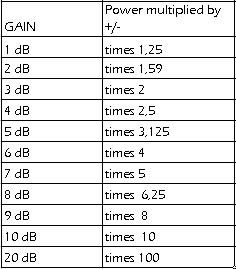
From this table you can discover:
When you have a dipole. and 100 watt and you have an 3 elements antenna with 6dBD gain you would need 400 watt on the dipole. to produce the same signal as with the beam.
With a calculating machine you could calculate how much loss in dB you have in a coax cable, for example at the transceiver side you are producing 100 watt
at the antenna side your measurements end up at only 80 watt:
100/80 = 1,25
1,25 log = 0,097 (just enter 1,25 in your calculator then press log.)
0,097 times 10 = 0,97 dB loss !
That is right because 1 dB was about a multiply of 1,25 So when we are talking about loss it is not times but you could divide it. 100 divided by 1,25 = 80 watt.
FRONT TO BACK (FB)
A beam antenna has besides gain another interesting feature it is called the front to back often shortened as FB.
It means nothing more than: How much weaker a station comes through at the back of the antenna compared to the front.
Looked close at this sentence you will notice it is compared to the front of the antenna, this is what many people forget.
It is only logical that with high Gain beams the Front to Back is higher as well cause the forward gain is higher!
The front to back is also expressed in dB, without an additional remark like dBI or the D for the above named reason.
It's value doesn't merely depends on the gain but on the complete design of the yagi (ALL element spacing's, ALL length, thickness) So you could design a beam with a high FB..sadly gain or bandwidth is often reduced so its a play between those three. (All is expressed in capitals because many think the reflector is responsible for the F/B..well he is not alone directors have a big influence as well
There are ways to improve the F/B, you could redesign the entire yagi of course but you could also add additional Reflector elements as we see quite often in the FM-radio spectrum (fuba-yagi) or place an additional director in front of the radiating element as done in the extra short versions described in chapter BEAMS.
Some manufacturers have extra reflector kits available for the "moonraker/lightning" series, your front to back will only become worse so do not use them.
BEAMWIDTH
This is where our gain primarily comes from!
We can distinguish two in beam width the horizontal or vertical.
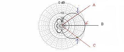
Take a look at the radiation pattern of a yagi below.
In the first picture we can see the HORIZONTAL BEAMWIDTH,(looked from above at the antenna) also called azimuth pattern.
The angle between A and B given in degrees are the points where the signal is 3dB weaker then the main lob.
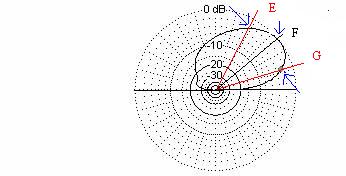
The VERTICAL BEAMWIDTH is the angle between C and D also given in degrees,(as shown in the second picture looked to from the side at the antenna)
also called elevation pattern.
Also here the points are 3 dB down the strongest point of the pictured pattern. (the strongest point was the take-off angle)
No comments:
Post a Comment