
Another vertical antenna for 30, 40 and 80 meters (and 160)
Introduction
This antenna does not imply any revolutionary technical concept and may not be even very original! The purpose of this is article is to describe a multi band DX-dedicated antenna offering a minimum of compromises (such as lossy traps), for the hams not having any high-support (70’ or higher) available. It may also be interesting to note the interest of MMANA for LC networks calculations.. The only unusual thing in this design may be the use of a 28/50 ohms broadband transformer (UNUN) to allow easy switching from a band to another (and avoid the use of an unpractical high value capacitor for the LC network).
General description
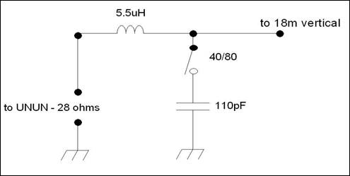
This is a ground mounted vertical, which works more or less as 5/8 on 30m, a half wave on 40 and a quarter wave on 80. The matching to the 50 ohms feeder is done at the bottom through a low-loss LC network (low pass configuration) combined with a 28/50 UNUN transformer.
The height of 60 feet was imposed by the 5/8 length on 30m and by the fact that it would have been difficult to match a real half wave on 40m. Easy band switching has dictated the use of the 28 to 50 ohms broadband transformer (28 ohms being the radiation resistance on 80m). As already mentioned, it would have been possible to avoid the UNUN, but this would have required the change of LC network configuration and the use of a high value capacitor for 80m (and a very low value for 30m).
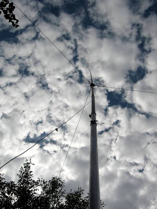 The antenna with a light wind.
Mechanical description
Mine is constructed using a 40’spiderbeam fiberglass mast extended at the top by a thin additional fiber fishing rod, and supported at the bottom with 2 sections of aluminium telescopic mast. A 2mm diameter wire is used along the fiber, except at the top where it is replaced by a thin 0.75mm wire. In the lower part, the wire is just maintained away from the aluminium section, which has no major technical implication and is a simpler solution than insulating the mast from the ground. It is just guyed with a single set of 3 nylon ropes located at approx. 8m AGL.
Anyway, anybody is free to use any technical solution to reach the required height. As a suggestion, the use of the newly released spiderbeam 60 feet mast would be ideal for this antenna. My antenna has 16 buried, 66 feet radials but this is of course not critical, as soon there are enough radials to get the radiation resistance around 28 ohms on 80m (of course more radials is even better). For ground losses estimation, you may look at the 1/4 resonnance (around 4.1Mhz without coil) where the radiation resistance should be close to 36 ohms - any higher value gives an indication about your ground losses (about 1.5 ohms on my setup).
The matching LC network.
My inexpensive experimental LC-matching network uses a « Red-army » adjustable coil (about 20 uH in total) and an air variable capacitor (about 20 to 300pF range/3kV insulation). It handles high-power without problem and there is no noticeable temperature elevation even after several hours of RTTY contesting (power limitation is just due to the UNUN specs and the CV insulation - especialy on 40m where the impedance is quite high). For CW contesting the use a single value of coil is needed, so the switching of the capacitor the only thing required to switch from 40 to 80. Covering the 3 bands in total just requires 2 values of L and 2 values of C.
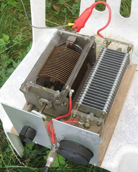
The experimental matching network. Switching from 80 to 40 CW just requires the disconnection of the capacitor, so it could be done using a HT relay controlled from the station. For portable contesting, using a 60 feet telescopic fiber mast, with the coil directly mounted around the mast (adjustable by compression/extension) would provide a simple, elegant and transportable solution.
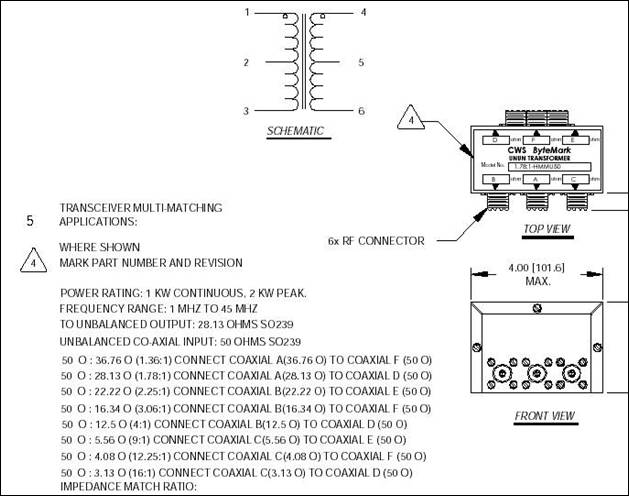
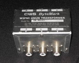
A quite unknown device: « the multi UNUN ». According to the connectors used for input/output, it allows matching a 50ohms line to a load of 36, 28, 22, 16, 12.5, 6, 4 or 3 ohms. Power rating 1kW continuous. This is a commercial version of a W2FMI design. Very handy, for verticals, but also for wire-beams - see http://f6irf.blogspot.com/2007/02/cn2ww-80m-wire-beam.html
Measured values for L and C for Z=28 ohms and a height of 59’ (my vertical lost 1’of length due to the retracting of 1 telescopic element after a storm)
80m SSB (3700 kHz) L= 3.5uH C=0pF (the capacitor is disconnected)
80m CW (3520 kHz) L= 5.5uH C=0pF (the capacitor is disconnected)
40m (7050kHz) L= 5.5uH C= 110pF. (the capacitor is connected on the antenna side)
30m (10125kHz) L=3.5uH C=40pF (the capacitor is connected on the antenna side)
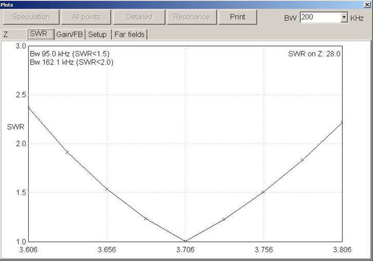
Simulated values, matching very closely the measured ones. On 40m the bandwidth at VSWR <1.5 is in the order of 300 kHz. Of course, no problem on 30m !
It is interesting to note that the measured values do closely match the values calculated with MMANA (On the MMANA model I have inserted a 1.5 ohms resistor, corresponding to the estimated ground losses).
L = 3.5uH Fo=3706kHz Z=28ohms, BW at SWR<1.5 : 95kHz ; BW atr SWR<2 162kHz.
L = 5.5uH Fo= 3520kHz Z= 24.62ohms, BW at SWR<1.5 : 71kHz ; BW at SWR<2 137.5kHz
Calculated values for 40 and 30m (see screenshots)

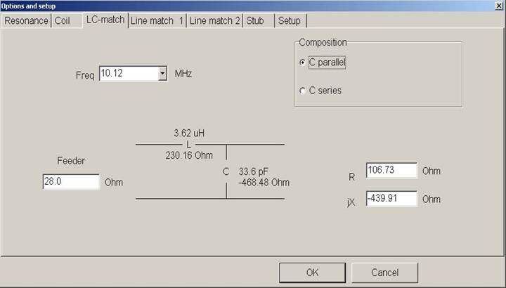
Here again the calculated values closely match the measured ones
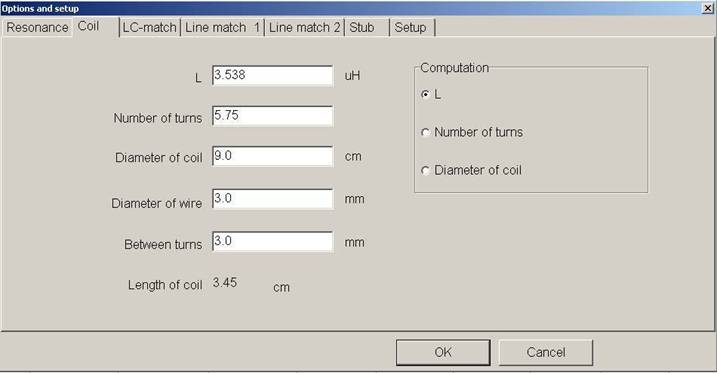
For information, MMANA also includes a coil calculator; those tools are making the design of a LC network a really easy task.
And without UNUN?
For information, folllowing are the calculated values for the LC-network for direct match to 50ohms.
For Zfeeder =50ohms (no UNUN) and low-pass configuration
10120 kHz : L=4.81uH, C=16.3pF (C antenna side)
7050 kHz : L=7.32uH, C=80.4pF (C antenna side)
3700kHz: L= 4.66uH, C=772pF (C feeder side)
3550kHz: L=6.32uH, C=906pF (C feeder side)
We see here the limits: on 30m the residual capacitor is likely to be a problem (although it should be possible to use a vacuum capacitor or high-pass configuration). On 80 meters the required value is very high, thus unpractical (the high pass configuration does not work on 80). This shows why the use of the UNUN is so interesting…
Results and performances
As it is the case for any vertically polarized antenna, the performances are, for a large part, linked to the ground quality and the efforts invested in the radials system. The following simulations have been done for an average ground and 16x 66’ radials. It is obvious that the same antenna, installed on a beach would provide far better performances. This said, compared to most commercial verticals this one offer a good bandwidth - including on 80m- combined with limited losses and high admissible power. Although the gain looks somewhat below optimum on 40 and 30m, the fact that the current maximum is « elevated » is an advantage in obstructed areas.
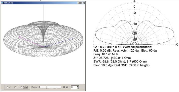
30m pattern -there is a little dissymmetry due to the mast. As pointed out by W4RNL in his article “the 5/8 mystic” (see references at the end ) in average terrain, the 5/8 length does not provide any miracle in terms of gain.

40m pattern: The main lobe is around 20degrees. What is interesting here is the high attenuation of NVIS signals (Nearly Vertical Incidence Skywave).
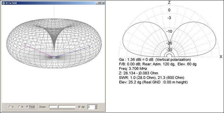
80m pattern: the small dissymmetry completely disappeared.
And the top band ?
With a coil value of 56uH and using the 6/50 position on the UNUN this aerial could also be used on 160m. However the bandwidth would be extremely restricted (around 10 kHz at VSWR <1.5 depending on ground losses). Even if it works (I worked the 3B7C expedition on 160 with this quickly implemented solution)it would be far more interesting to add some top loading. For example a simple 12m wire would decrease the required L to 22uH, would increase the radiation resistance to about 15 ohms and the useful bandwidth to about 20kHz. Obviously the performances on 30 and 40m would require the top loading wire(s)to be folded back along the mast. I just mention this for information, as this is not the purpose of this article. You can read more about "top loading" in the W4RNL pages http://www.cebik.com/radio.html
Conclusion
I must admit that during years, I used only horizontally polarized antennas. Even tough, in average terrain, a vertical is unlikely to outperform even a simple dipole if it is at least at a ½ wave above the ground; a vertical still has some interesting properties for the modest DX-man or contester, not having sufficient space or consequent supports. First it is omni directional which is interesting if you don’t have the possibility of installing a rotating antenna, and secondly it provides a useful attenuation of NVIS signals.
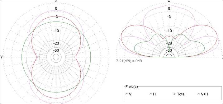
Illustration on 30m: At « long DX angles » (10deg) even a dipole at 20m outperforms the vertical only on 50% of the directions. In purple an inverted V- dipole with apex at 66 feet, in red at 40 feet and in green the vertical. Taking into account the investment, the vertical is far from being ridiculous as you need to rotate the dipole to get the full benefit. The comparison is even more in favour of the vertical on 40 and 80m.

Compared DX-performances (10deg take-off) of a dipole at 66 feet and the vertical. Obvioulsy the vertical is not recommended for domestic contests.
Despite the modest gain figures, this antenna allowed me to work the recent 3B7C expedition quite easily on 2 modes per band on 30, 40 and 80 and in CW on 160. In the last CQWW RTTY, and although I spent only 27 hours all bands it provided 72 countries on 40 meters, better than what I had done in 2005 with a dipole at 66 feet (and a total time investment of 40 hours). Of course it does not proove anything, but after several months of use, I got to the conclusion that this antenna was one of the best I ever used at home. Of course, compared to a a high yagi it can't be "the absolute pile up breaker”, but in a few month of use it allowed me to considerably improve my DXCC score on the bands that it covers. I am just dreaming about using this antenna somewhere on a beach…
Good DX’ing !
No comments:
Post a Comment