
Amateur Radio (G3TXQ) - A family of wire beams
During the computer modelling and experimental work I carried out to develop the broadband hexbeam described elsewhere on this web site, it became evident that this antenna is just one of a large family of antennas which share a common structure and which can be "multibanded" using construction techniques similar to those commonly used with the Hexbeam.
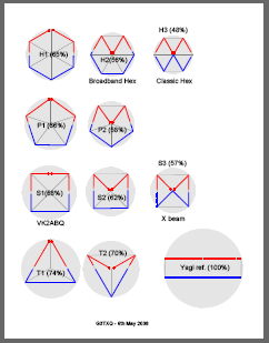
The drawings on the right (click for the full-size version) show a subset of all these 2-element wire beam arrangements based on 3-sided thru 6-sided figures. The common characteristics of this subset are:
- The geometries are "regular" - ie a perfect square, an equilateral triangle etc.
- The feed points and changes of wire direction occur at support spreader positions, or centre post positions, where there is good mechanical support. [The one exception to this rule is configuration S1 where the feedpoint has been shown midway along one side to include the well-known VK2ABQ antenna.]
- Note that the combinations where the Reflector is bent back towards the centre of the antenna whilst the Driver follows the perimeter of the shape, have not been included. Computer modelling shows that this is an unattractive arrangement which produces narrowband performance and worse SWRs compared to the same-size "Bent-Driver/Perimeter-Reflector" arrangement.
The diagrams were drawn using a simplistic scaling which assumes that the total wire length for each shape will be about the same. The (%) figure shown on each diagram is the relative turning radius referenced to a full-size 2-element Yagi.
Some of the options are well known to us: H2 - Broadband Hex; H3 - Classic Hex; S1 - VK2ABQ; S3 - X beam. Others are less familiar. The classic X-Beam appears to have little to commend it - it is marginally larger than the broadband Hexbeam and its Bent-Reflector can be expected to make its F/B performance relatively narrow-band.
The "Bent-Driver/Perimeter-Reflector" options - H2, P2, S2 and T2 - are attractive. They deliver a useful reduction in size without the narrowband performance inherent in the "Bent Reflector" options, and they provide a good match to 50 Ohms. They were selected for further detailed performance modelling.


 A systematic approach was taken to "optimise" the wire dimensions for 20m versions of the four antennas:
- The reflector length was adjusted to place the peak F/B at 14.150 MHz.
- The driver / reflector end spacing was adjusted to achieve a peak F/B ratio in excess of 30dB whilst trying to keep the worst case SWR around 2:1.
- The driver length was adjusted to try to place the minimum SWR mid-band.
The final dimensions, using #16 gauge wire, which evolved from Free Space performance optimisation, were:
- Hex beam: half-driver 219", half-reflector 207.8", end spacing 30", turning radius 130"
- Pent beam: half-driver 219", half-reflector 208.7", end spacing 24", turning radius 135"
- Square beam: half-driver 218", half-reflector 210.5", end spacing 22", turning radius 145"
- Tri beam: half-driver 212", half-reflector 212", end spacing 40", turning radius 170"
The Free Space performance of the four antennas is compared below, alongside the performance of a full-size 2 element Yagi for reference:


 Observations
- The Hexbeam, the Pentbeam and the Square beam are each capable of providing a peak F/B ratio in excess of 30dB, and a worst case F/B ratio of 12dB across the 20m band. The F/B performance bandwidth of these three antennas is very similar - the more "open" shape of the Hex and Pent reflectors compensating for the reduced size of these antennas compared to the square
- The "closed" shape of the Tribeam reflector produces relatively narrowband F/B performance
- The Hexbeam, the Pentbeam and the Square beam have similar SWR characteristics. With further minor optimisation it would be possible to achieve a worst case SWR below 2:1 for all three of these antennas
- It proved impossible to place the Tribeam’s minimum SWR mid-band, or to get it below 2:1 at the lower band edge.
- All four antennas exhibit the fall-off in gain with increasing frequency which seems to be typical of end-coupled wire beams. There is a spread of approximately 0.5dB in forward gain at the bottom of the band between the four antennas. At the top of the band, the spread between the Hexbeam, the Pentbeam and the Square reduces to 0.2dB; however the gain of the Tribeam has fallen much more dramatically.
Conclusions:
- All four antennas provide useful beam performance in a space significantly smaller than a full-sized 2-element Yagi.
- They lose out to the Yagi on forward gain, but have much superior Front/back ratios.
- The Tribeam is probably the least attractive of the four antennas. Although it requires only 3 support spreaders, its performance bandwidth is significantly inferior to the others and it has an assymetric SWR curve - characteristics it shares with the Classic Hexbeam. It also has the largest turning radius at 170".
- The three remaining shapes have very similar F/B and SWR performance to one another. The square shape provides marginally the best forward gain and requires only 4 support spreaders; however it is the largest of the four antennas. The Broadband Hexbeam is the smallest of the antennas considered, but it requires 6 support spreaders and has marginally the lowest forward gain. The Pentbeam size and performance sit neatly between those of the square and hexagon shapes.
No comments:
Post a Comment