
Amateur Radio (G3TXQ) - UnUn experiments
A. Introduction
Multiband antennas comprising a non-resonant length of wire that is fed via coax and an impedance transforming UnUn have become very popular of late - they are convenient and a low cost alternative to siting a remote tuner at the base of the vertical. The inclusion of the UnUn is designed to limit the high SWRs that would occur on some bands, and thereby avoid some of the very high coax losses which might otherwise occur. This page describes a series of experiments I carried out to try to understand better how typical UnUns perform in this application.
B. Antenna and SWR
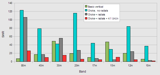
The antenna comprised 40ft of insulated wire taped to a fibreglass fishing pole mounted vertically at ground level on the corner of my garage. It was fed via a length of RG58 coax from the nearby shack. The following chart shows the measured SWR on the 80m thru 10m bands under four different sets of conditions:
The green bars show the performance with the feed coax connected directly to the vertical; no UnUn was used, there was no connection to any ground system, and no RF choke was used. The SWR varied from a low of 5.9:1 on 10m to a high of 49:1 on 30m. Given that no ground system was used we might wonder what forms "the other half of the antenna":
The answer is clear when we add a common-mode choke at the feedpoint to prevent current flowing on the outside surface of the coax braid - we get the performance shown by the turquoise bars. With the exception of the 30m and 15m bands all of the SWRs are worse - often by a very large margin. This demonstrates that, as expected, if you have no ground system the coax braid becomes an integral part of the antenna system.
Next I added a modest radial system comprising six 25ft wires laying on the ground and arranged as evenly as I could within the constraints of my back yard; the results are shown by the grey bars. On all bands except 30m there is an improvement in the SWR - on most bands a very significant improvement.
Finally I added at the feedpoint a 4:1 UnUn comprising 12 bifilar turns on a T200-2 iron dust core; the results are shown by the red bars. Other than on 15m the UnUn produces a further reduction in SWR which never exceeds 26:1 on any band.
C. UnUn variations
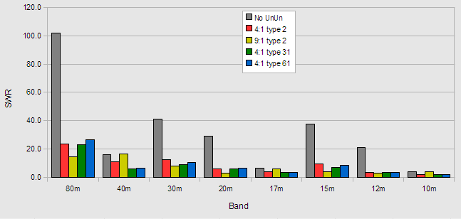
I next decided to investigate how UnUns of different designs compared. I wound a 9:1 UnUn comprising 9 trifilar turns on a T200-2 core, a 4:1 UnUn comprising 12 bifilar turns on a FT240-61 core, and a 4:1 UnUn comprising 12 bifilar turns on a FT240-31 core; here are the results:
Clearly, introducing any of the UnUns makes a dramatic improvement to the SWR on most of the bands; the exceptions are those bands where the SWR is already low. Choosing between the various UnUn designs is not easy - one does better than the others on a few bands, but is worse on others. Taken overall, with this particular antenna the 9:1 UnUn wound on Type 2 material probably has the edge.
D. Impedance transformations
What is not obvious from these results is just what impedance transformations are being introduced by the UnUns. Particularly at the lower frequencies, a combination of the low permeability of iron dust material and the reactive antenna impedance means that the impedance transformation ratio is far from the 4:1 or 9:1 that might naively be assumed.
For example the 4:1 UnUn might be expected to transform an 80m load impedance of 12-j236 to 3-j59; in fact it transforms it to a wildly different 367+j480. This arises because the UnUn is far from being an ideal transformer, and its low inductive reactance combines with the capacitive reactance of the load to form a tuned circuit which, if close to resonance, will produce impedance transformations far removed from the ideal. Fortunately, this does not matter in this application - the actual impedance is largely irrelevant because a tuner is used at the shack to provide a match to 50 Ohms. But it does mean that any theoretical evaluation of these types of antenna system is suspect if it assumes that the UnUns behave as ideal impedance transformers.
E. UnUn Losses
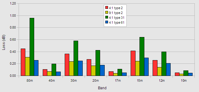
A further consideration with the UnUn is what loss it introduces to the antenna system. Knowing the UnUn secondary impedance and the antenna impedance, we can estimate the losses introduced by each design:
Notice that losses with the Type 31 material are significantly higher than with any of the other designs. This is to be expected because the complex permeability of the Type 31 ferrite mix has a large resistive component; this is an advantage in common-mode choke applications, but not so useful when acting as the core of a transformer potentially handling high voltages.
Of the remaining designs, the 4:1 UnUn wound on Type 2 material probably has the highest loss. To put the numbers in context, a loss of 0.4dB means that the safe power dissipation of a T200 size core would be reached at an applied average power level of 110W.
With all the UnUn designs, loss becomes much higher at low frequencies if the antenna is shortened; so be very wary of the power-handling claims for UnUns wound on T200-2 toroids and used with short antennas.
It's also worth noting that at low frequencies, where the antenna is electrically short and its reactance is high compared to its radiation resistance, high voltages can be generated across the UnUn at modest power levels. For example, if this 40ft antenna were radiating 100W there would be a voltage of over 1kV pk across the UnUn; well-designed UnUns will have winding insulation which takes account of this.
F. Overall performance
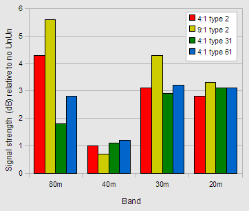
Just because one design of UnUn has slightly more loss than another doesn't necessarily mean that its transmitted signal will be weaker; if that design results in a lower SWR on the feedline - and therefore lower feedline loss - it could still produce the net greater signal. To take account of these factors I measured the signal picked up from the antenna by a local receiver, and swapped between the UnUn designs. The bar chart shows the results referenced to the signal from the vertical without an UnUn. Again, with this particular antenna, the 9:1 UnUn wound on Type 2 iron dust material gives the best overall results.
Most of the signal strength results can be explained by reference to the preceding charts. For example, on 80m the 9:1 UnUn produces the lowest SWR on the feedline, and itself has the second lowest UnUn loss; so we might expect it would produce the highest signal strength.
G. Conclusions
- An UnUn can significantly reduce the range of SWRs on the coax feedline - and therefore reduce feedline losses - on a majority of bands
- All four UnUn designs produced a broadly similar SWR reduction, but with this particular length of antenna the 9:1 UnUn had marginally the best overall performance
- UnUns can be lossy, particularly at low frequencies where the antenna is electrically short, and small cores can easily be overheated at quite modest transmit powers
- Lossy ferrite mixes are a poor choice for this application
- Typical UnUns wound on iron dust cores are far from being ideal impedance transformers at low frequencies when handling the reactive loads represented by electrically short antennas. Any theoretical analysis which assumes they produce 4:1 or 9:1 impedance transformations is suspect
No comments:
Post a Comment