

Last Modified: June 14, 2012
Contents: Basics; The Band Coverage Myth; The Choke Myth; What is 3dB?; The DX Myth; The Gain Myths; The Reciprocal Myth; The Efficiency Myth; The Power Myth; Ground Loss Myths; Radiation Pattern Myths; The NVIS myth; The SWR Myth; The SWR vs. Resonance Myth; The Coaxial Myths; The bandwidth Myth; The Hole Myth; Conclusion;
Basics
It's best not to know very much, than to know a lot of things which aren't true.
There is so much misinformation floating on the Internet about antennas in general, and mobile antennas specifically, it is not surprising many newcomers are confused. Although some of the information presented here is in other articles on this web site, it is best to set them out here in an effort to correct some of the more popular myths. While some of them can be applied to base station antennas as well, the thrust here is aimed at HF mobile antennas.
Terms used here are the same as those explained in the Antenna Efficiency article, thus it should be read first. Readers should also acquaint themselves with with the different types ofgrounds, and ground planes.
☜Return☜
The Band Coverage Myth
Advertising hype to the contrary, it is difficult to design a remotely-tuned antenna to cover 80 through 10, much less adding 160 and 6 meters to the mix! There are many reasons why this is so, but not the least is physical length. A full-length 1/4 wave, unloaded antenna for 6 meters will be about 54 inches long, and may be only 48 to 50 inches if the mast is large like those of most remotely-tuned antennas. This is slightly longer than the base/coil assembly of most screwdriver antennas.
On 10 meters, a full-length 1/4 wave, unloaded antenna is about 96 inches long, but again may be somewhat shorter due to the mast size. Depending on the antenna brand in question, covering 10 and 12 meters will likely require installing a shorter whip. When it doesn't, it means the overall losses are higher than they should be.
Any 160 meter mobile antenna will have very poor efficiency, perhaps as low as .5%. A really good one perhaps 1%. Part of the issue is the requisite inductance of the coil. Even an antenna 13 feet in overall length will require an inductor in the neighborhood of 600uH. Using the very best construction techniques, maintaining a Q of even 100 is difficult. As a result, the coil losses are great enough, that impedance matching isn't necessary in most cases. When it is, the amount of reactance required will be vastly different than that required for an 80 through 10 meter antennas.
Thus, claiming full coverage from 160 through 6 meters, even if it requires changing the whip length on the higher bands, is meant to sell antennas. And that's no myth!
☜Return☜
The Choke Myth
One of the most popular ancillary mobile devices is the automatic screwdriver controller. They're great safety devices too, because no intervention is required by the operator, save for pushing a tune button. All of them require that the RF imposed on the motor leads must be properly choked. While it is true that some controllers will still function with a minimal choke, there is a hidden facet almost everyone misses.
The perceived noise level we all contend with, comes from both man made noises (RFI), and nature (background ground static). The consensus of opinion is, that all of this noise reaches the receiver via the antenna. This is easy to confirm by disconnecting the antenna from the back of the radio. However, does it all really come from the antenna? The answer is, no! If you've read the Common Mode article, you already know that the coax cable can be a major contributor. It pays to remember, that every mobile installation will have some level of common mode, due in part to the excess ground losses we all deal with. If common mode can get out, it can get in too!
Here's some food for thought. Due to a preponderance of digital electronics, the insides (passenger area) of a modern vehicle is almost as RF noisy as it is under the hood! As a result, our inadequately choked control cable and coax are picking up the harmonically-rich, digital noise. This significantly reduces the SNR, and our ability to hear, even if they're not (directly) in the receive bandpass. The bottom line is, if you can't hear them, you sure can't work them!
☜Return☜
What's 3 dB?
One very common comparison is the dB difference between one HF antenna, and another. As in; Oh, it's just 3 dB, or half an S unit, big deal! It may sound like no big deal, but it can be! What's lost in the translation is the effect 3 dB can have on the signal to noise ratio (SNR) on either end of the contact. In fact, sometimes, just 1 dB is enough that no copy, can turn into perfect copy. The real issue at hand, however, is just how much effort you want to put into your mobile installation. If you're satisfied with yours, then great, but please don't use the trite justifications listed below.
☜Return☜
The DX Myth
No doubt, the single, most often used reference (past the point of triteness) is the number of DX stations said antenna installation garnered. How or why this practice got started is an unsolvable mystery. As condescending as it may sound, amateurs who use their DX contacts as a reference, typically have the poorest of installations, and the worst of operating skills. If your intent is to be a LID (very poor operator), then visit this web page.
Just for the record, the number of DX stations worked has no correlation to any antenna parameter, and here is why. Under the right band conditions (good propagation and low background noise level), it is possible to make on-air contacts, even DX ones, with as little a one milliwatt (1/1,000) of Effective Radiated Power (ERP). It shouldn't come as a surprise then, that on-air contacts can be made with 500 milliwatts (1/2 watt) of ERP. In fact, this is about the ERP of an average spirally-wound and/or short, stubby HF mobile antenna on 80 meters (with 100 watts input).
Compare this with a decent quality screwdriver antenna, properly, and solidly, mounted where the ERP is about 5 watts on 80 meters. The difference is a little more than one S unit (assuming you have an accurate S meter). Therefore, some argue that a lowly hamstick or short, stubby screwdriver is an adequate HF mobile antenna. But is it? Well, that depends on too many (usually overlooked) factors.
One of those factors is the Signal + Noise/Noise ratio (SNR) generated in the receiver's front end. Most modern HF mobile transceivers will provide a 10 dB SNR with a signal as little as .15 microvolts (uV) above the noise floor. As long as you can generate that level on both ends of the contact, you're home free. Since we also have to deal with background noise level on whatever band we're using, in the real world, it might take 10 times that signal level (1.5 uV) above the noise floor, and sometimes a great deal more!
So, here's the question you need to ask yourself; Will increasing my ERP by just 10 dB really be worth the effort? Perhaps an even more important question is; Will increasing my S+N/N ratio (SNR) by 10 dB worth the effort? The answers to both are, absolutely!
There is a antithesis in the second question. That is, the better the SNR, the less perceived the noise portion is. This is true whether it be man or nature made. This fact alone should give you enough food for thought to make a proper antenna selection.
☜Return☜
The Gain Myths
There is no viable methodology to achieve positive gain in an HF (160 through 10 meters) mobile antenna. But that fact doesn't stop some manufacturers from claiming otherwise. For example, there is a very-expensive one made in the middle east which resembles a large luggage rack which mounts atop a vehicle. It is configured as a magnetic loop, and is remotely tunable. Rated at 150 watts PEP, the manufacturer claims it has 9 dB of omnidirectional gain, but doesn't give you a qualifying suffix, so the figure is meaningless. They further assert it has NVIS capability, which it doesn't. All of their palaver is easily disproved by modeling the antenna with EZNEC or NEC5. If you do, you'll also find the efficiency is less than 3%, best case!
There are at least two manufacturers here in the U.S. making spirally-wound, 6 foot long HF antennas, claiming they have gain because they are a 5/8 wave length. The may indeed have wire that long wound around their fiberglass core, but that doesn't make them a 5/8 wave gain antenna. In fact, if you could wind 100 feet of wire around a 4 foot long fiberglass mast, the electrical length would still four foot long. When you see claims like these, go elsewhere.

None the less, many amateurs purchase VHF antennas based solely on their advertised gain. Adding insult, the published gain figure typically doesn't have a quantifying designator. That is to say, they just list the dB, and not the dBi or dBd. The i stands for isotropic, and the d for dipole. Without one of these designators, the figure is meaningless.
One enterprising Pacific Rim antenna company's brochure, states in fine print that their gain figures are based on a comparison to a standard hand held antenna. That's a rubber ducky! What's more, the phasing coils used are miniscule, and any real gain they might exhibit, is all but lost in the phasing coils.
There is more to the story. Doubling your effective radiated power (+3 dB) will not magically double the distance you can communicate over, especially when using FM. Further, there is a good case to be made about using unity gain (Ø gain) antennas in a metropolitan area. The reason is simply this. The HAAT (height above average terrain) of the repeater, versus that of a mobile, requires radiating power at higher angles. Gain antennas achieve their gain by compressing the pattern, thus their high angle radiation is reduced. As a result, 1/4 wave, unity gain antennas perform better in these situations, than their higher-gain counterparts do.
Lastly, some Pacific Rim antennas are so poorly designed, and made, that one good slap from a errant tree limb will render them useless. Again, you need to ponder more than just a gain figure when making an antenna selection, especially a VHF one. By the way, that includes the way they're mounted. In short, if you want the best performance, you have to drill a hole!
☜Return☜
The Reciprocal Myth
The electrical properties of any given antenna are reciprocal. For example, any gain (or lack of it) they exhibit applies equally to transmit and receive. However, in the real world, theperformance between transmit and receive is not reciprocal. This is due to a variety of reasons, not the least of which is takeoff angle. Further, improperly installed HF mobile antennas may have their radiation pattern overly distorted, which exacerbates the performance difference. There are many more variables too. We mentioned SNR, and ERP above, and to it we add; atmospheric noise, propagation phenomena, and even ground losses, to name a few.
In fact, the difference between transmit and receive performance can be rather extreme; sometimes you can hear better than you can be heard, and sometimes the reverse is true. So when you make a pat statement like, I can work any station I can hear, you're kidding yourself. However, if the statement is factual, you need a better antenna and/or mountingscheme!
☜Return☜
The Efficiency Myth
High-frequency mobile antennas are not perfect performers, regardless of their owner's DX claims. For example, if you were to mount a 1/4 wave, 10 meter resonant antenna (8.2 feet long), made of solid silver rod, in the middle of the roof of an average vehicle, the efficiency would barely meet 90%. In the real world, it is more like 80%. In other words, 100 watts might go in, but only 80 watts is radiated. As the frequency is lowered, the efficiency drops, and rather drastically. Fact is, the average commercially-manufactured, HF mobile antenna is about 1% efficient on 80 meters. That's not a misprint; 100 watts in, only 1 watt out, and you only get that if you mount it correctly! Sure puts new meaning into QRP operation!
Short, stubby antennas, are much worse, as are thin, spirally wound ones. It is not uncommon for the efficiency level for these antennas to drop below .3% (that's point three percent!) on 80 meters, and well below this figure on 160 meters. Mount one of these antennas on a clip or clamp mount, and you can easily halve the figure; .15%.
Length matters, as does adequate coil Q, and mounting height. Do everything right, and 80 meter efficiency can be ≈6%. Don't kid yourself, this isn't as easy as it sounds. It takes length (>12 feet), a high Q coil (300+), no doubt a cap hat, and a high mounting location with lots of metal mass under it. One thing is for sure, it is difficult to explain (and justify) these requirements when the DX myth is used as a yardstick.
☜Return☜
The Power Handling Myth
For the most part, the maximum power any given mobile antenna can handle is based solely on the Q of its coil. Depending on that Q, at some given power level, the I2R losses will exceed the dissipation loss capabilities of the coil, and the coil will fail. In some cases, the dielectric strength of the insulation either on the wire, or its supporting structure, can be exceeded. When it is, an arc can form which can also cause the coil to fail. Contamination from road debris and water exacerbates the problem.
As pointed out in the Antenna article, there are several screwdriver antennas rated at 200 watts PEP (or less!). Although they get warm during normal operation due to the rather high resistive coil losses (low Q), typically there's no permanent damage done. However, driving one with much more than 25 watts during tuning will damage the coil assembly beyond repair! As above, the scenario is exacerbated by proper mounting (reduction of ground losses).
Amateurs typically purchase an antenna with a power rating perhaps twice their transceiver's capability. That's a step in the right direction, but the truth is, there will still be I2R losses turning transmit power into heat. Thus, it behooves you to choose an antenna which has considerably more power handling capability, than you plan to use. However, there is a caveat; Far too many antenna manufacturers over-rate the power handling of their antennas.
As I point out in the Amplifier Care & Feeding article, here are a few antennas to avoid. Any vinyl covered one especially those with large metal end caps; Any screwdriver antenna with more than 10 turns per inch, or smaller than 2 inches in diameter, or wound with less than size 14 awg wire. This includes stubby screwdrivers (except the 680S Scorpion), any Hamstick®, any Hustler®, the Opek®, and any antenna where the loading coil is mounted higher than 60% of its length.
☜Return☜
Ground Loss Myths
A vehicle is not a ground plane for an HF antenna. Rather, it acts like a capacitor between the antenna, and the surface under the vehicle in question. That surface, whatever it is, forms the actual ground plane, albeit rather lossy. Depending on the reference, the stated ground loss for an average vehicle varies between 2 and 10 ohms (10 through 80 meters). The real world figures are closer to 5 to 20 ohms. In other words, equivalent to a capacitor with a value of between .004 uF to .002 uF.
One of the reasons ground plane-less verticals (no radials, perhaps just a pipe or ground rod) do not perform well, is because the current returned to the source is forced to travel though lossy ground. A similar situation exists in a mobile installation. That is to say, some of the antenna current returning to the source flows through the surface under the vehicle, rather than through the vehicle itself. This fact increases ground losses.
One of the base-station work-a-rounds, is to elevate the antenna away from the poor conducting ground surface, and use an artificial ground plane; radials in other words. However, we don't have that luxury in a mobile installation. There is one thing we can do, and that's raise the antenna as high as possible on the vehicle, consistent with local height restrictions (legal, trees, wires, etc.). Doing so reduces the coupling between the antenna and the surface under the vehicle, which increases the current flow through the body of the vehicle, and reduces the overall ground losses. It should be noted that a proper mobile installation will always have more ground loss than a proper base station installation.
The coupling between the super structure of any vehicle, and the surface under it, is not consistent. Thus there will always be standing waves between them. Just about every nuance you can think of can, and will affect these standing waves. These standing waves are, in essence, the main cause of the ground losses in the first place. Please note, we're not talking about the standing wave ratio (SWR) of the antenna! It should also be noted that you can't measure these standing waves directly. Therefore, although they are represented as part of the input impedance of the antenna in question, changes therein cannot be assumed to be a reduction, or increase, in either these standing waves and/or in ground losses, without a thorough understanding of the other parameters involved. Field strength measurements will give you a better comparison of the changes, but here too they have to be carried out in a scientific (all factors normalized) manner, or the results will be just as ambiguous as any input impedance measurement.
The effect can be shown graphically by using antenna modeling software like EZNEC. However, modeling programs often don't calculate ground losses accurately, even in ideal situations. When they're used to model vehicle installations, ground loss calculations are even less exact, due in part to the complexity of accurately modeling a vehicle's superstructure. Thus, the often-quoted data relating to mobile HF antenna models is often contrary to empirical testing.
Incidentally, the number of modeling segments in EZNEC required to duplicate an average vehicle's real-world condition, exceeds 200. A fact which requires the full-boat, commercial version, not the free, downloadable version. Even then, the accuracy can be poor if the ground loss figures are incorrect.
There's another important item with respect to ground losses which needs addressing, and that is consistency in ground conductivity. While the mean deviation over a large statistical area may be fairly narrow, over a small statistical area the mean deviation can be rather drastic. Adding insult, mobiles operate on paved surfaces for the most part, and road surfaces are even more inconsistent than soil surfaces.
Lastly, the mean deviation in soil conductivity changes as the moisture content, and surface temperature of the ground changes. In fact, the changes are often great enough, that you can measure the difference in input impedance between morning, and evening. This fact is yet another reason antenna shootouts are not nearly as definitive as organizers would lead you to believe.
Here's one more important point to ponder. Most amateurs wouldn't think about installing a base-station dipole antenna with the elements parallel to one another (spaced 6 to 8 inches apart), with the feed point a few inches off the ground. Yet, that is essentially what they're doing when they mount an HF mobile antenna on the back of a van or SUV utilizing a trailer hitch type mount. They fact you can make contacts with such a setup doesn't mean much.
☜Return☜
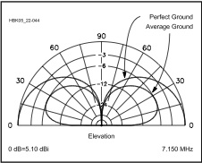
Radiation Pattern Myths
The angle of radiation from a horizontal antenna, is rather dependant on the ground conductivity under the antenna. This fact is why height above true ground is so important tohorizontal antennas. However, when it comes to verticals, height isn't so important, as long as the ground losses are low. There are a couple of ways to accomplish this with a base-station vertical. One is to lay out a bunch of radials (at least 25 or so) under the antenna, or raise the antenna off the ground, and use a lessor number of elevated radials. Rather than insert a book-length dissertation at this point to explain why this is so, I suggest you read Rudy Severns', N6LF, series of white papers on the subject. If you want the short course, read his PowerPoint® presentation.
We can reduce the ground losses in a mobile installation by increasing the mounting height of the antenna. Two things happen when you do. First, the resonant frequency increases, due in part to a reduction in the capacitive coupling between the antenna, and the surface under the vehicle. The ground losses decrease, as does the input impedance, basically for the same reason. The reduction in ground losses effectively increases the antenna's efficiency; a worthy endeavor! Incidentally, this is why good installations require antenna matching networks (antenna input impedance less than feed line impedance), and poor ones typically do not.
The another common myth is the level of distortion in the radiation pattern caused by the body of the vehicle. Yes, the pattern is distorted, but not nearly to the level most folks believe. Regardless of the aforementioned shortcomings of modeling software, they're fairly accurate in modeling the radiation pattern. In fact, they fairly mimic empirical testing. That is, if folks are willing to go through the necessary, 200+ machinations to describe the vehicle's superstructure to assure even a modicum of accuracy. If you do the tedium, you'll discover the differences are seldom more than about 3 dB. However, the difference may be somewhat greater when modeling antennas mounted low on the back of vans and SUVs. I might add, if the modeled (or real world) measurements exceeds ≈6 dB, then a higher, less lossy mounting location and/or style is in order.
Proponents often challenge the aforementioned findings, by driving around in circles as a test of the theory. They should remind themselves, that instantaneous changes in atmospheric propagation, and changes in ground conductivity, are far more telltale than the distortion caused by the body of the vehicle.
There is a related myth which needs to be dispelled. That is, that ground conductivity in areas near the ocean, account for increased propagation and signal strength, and even lower angles of radiation. The truth is, the affect is largely a result of a clear horizon unencumbered by structures, and flora, albeit with a slight decrease in ground losses. Again, localized ground losses have no measurable affect on the radiation angle or (the) far-field pattern!
\☜Return☜
The NVIS Myth
During WWII, the German army used wire beam antennas, wherein the reflector was laid on the ground, with a slightly longer radiating element closely spaced above it (≈1/10th wave length). The resulting radiation pattern contained a lot of high-angle energy. The description used to designate the radiation was Raumwelle Nahe Vertikale. Which translates to Near Vertical Incident Skywave (NVIS).
At about the same time, U.S. Army intercept operators noticed they could sometimes hear the German stations better when they bent over the whip antenna attached to their command sets. But it wasn't a result of producing an NVIS radiation pattern. Rather, it was a result of capacitive antenna loading which reduced the level of the incoming signal, and increased the S+N/N ratio making copy easier. The same effect can be demonstrated by turning down the RF gain in the presence of a high noise level.
After the hostilities were over, some hapless fellow combined these two, really unrelated, items creating the myth that bending over the whip of a mobile antenna produces an NVIS pattern. Of late, the Internet has allowed this myth to propagate (excuse the pun) beyond all belief and reason.
There are at least 10 web sites, even a military one, dedicated to NVIS. The misinformation on all of these sites, is roughly based on the same set of flawed data. It seems, after all, once something gets into print, especially on the Internet, it accepted as gospel. In any case, the myth can be easily dispelled by modeling a vertical antenna with, and without, a bent-over whip. Be careful, however, as there will be changes in the input impedance, and resonant frequency. Proponents misconstrue these changes as support for the myth. Or, they site S meter readings, which are suspect at best.
I should add, NVIS is very difficult to accomplish at frequencies higher than about 5 MHz, and impossible over 8 MHz. Yet, at least two antenna manufacturers openly state their antenna's NVIS capability up to, and including, 30 MHz. Perhaps the only bigger myth, is the SWR myth!
☜Return☜
The SWR Myth
If you have the acreage, the right kind of test equipment, a fair knowledge of antenna theory, some cash liquidity, and a whole lot of time on your hands, you can even measure the signal strength at any given angle of radiation within a few percentage points. Alas, most amateurs don't have these facilities, so they resort to the SWR myth.
Measuring the SWR is an easy task, so I suspect this is why neophytes often use SWR as a means of quantifying and qualifying their antennas. The truth is, a low SWR means nothing other than your transceiver will be happy! Maybe!
One thing is for sure, it will not give you the true resonant point, unless the antenna's input impedance (at resonance) is exactly R50 +jØ; a very rare occurrence indeed! Fact is, it is possible to damage some transceivers even though the SWR appears to be low.
☜Return☜
The SWR vs. Resonance Myth
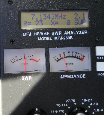
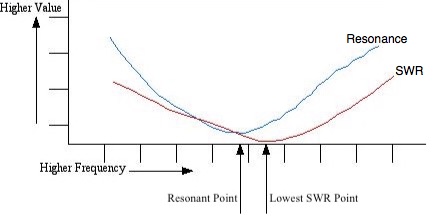
By definition, an antenna's resonant point will be when the reactive component (j) is equal to zero (X=Ø, or +jØ). At that point in our example shown at left, the R value reads 23 ohms, and the SWR readout will be 2.1:1 (actually 2.17:1). If we raise the analyzer's frequency slightly, the reactive component will increase (inductively) along with an increase in the resistive component, hence the SWR will decrease, perhaps to 1.4:1. In this case, the MFJ-259B is connected to an unmatched, screwdriver antenna mounted on the left quarter panel, and measured through a 12 inch long piece of coax. This fact is shown graphically in the image at right.
Depending on the transceiver in question, the resulting reactance may or may not cause any major problems, but it is still advisable to properly match your antenna. It should be noted, however, if your antenna doesn't require matching (input impedance ≈50 ohms), you need a better antenna and/or mounting scheme!
☜Return☜
Coaxial Myths
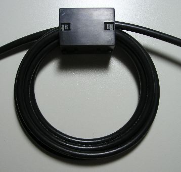
Coaxial myth two: Using the best grade of coax money can buy, will be worth the expense. Not! There are two aspects of this myth. First, the the length of coax used in the average mobile installation, seldom exceeds 10 feet. Thus the difference between say RG213, and RG8X, is less than .25 dB! Ah, but there is a hidden facet as well! As mentioned above, it is very important to properly choke off common mode currents from coaxial feed lines, especially mobile ones. In order to duplicate the common mode choke shown at right (7 turns, 3/4 inch ID, mix 31 split bead, ≈2.2 kΩ @ 10Mhz) on RG213, would require 49 similar split beads. That's about $250 worth, instead of just $5!
☜Return☜
The Bandwidth Myth
In a general sense, with respect to HF mobile operation, wider bandwidth usually relates to lower efficiency, but not always as some believe. For example, if we use a shorted stub to impedance match an HF mobile monoband antenna, the 2:1 bandwidth edges will expand, perhaps by double. This is due to the frequency versus reactance curves of the stub, and the antenna being opposite of one another. However, like capacitive matching, stub matching is monoband in nature.
Worse, one manufacturer taunts the bandwidth of their high-powered coils as a selling point. The truth is, the large end caps reduce the Q of the coils below that of their standard sized ones. The point here is, be careful of advertising claims about bandwidth.
This always raises a question about what the 2:1 or 3:1 bandwidth should be. Well, here's the truth. Two, otherwise identical installations, will have different bandwidths. Why this is so, lies in what comprises an (relatively speaking) efficient HF mobile antenna.
Lastly, considering the ever-increasing popularity of remotely-tuned HF mobile antennas, the bandwidth, 2:1 or otherwise, becomes all but moot.
☜Return☜
The Hole Myth
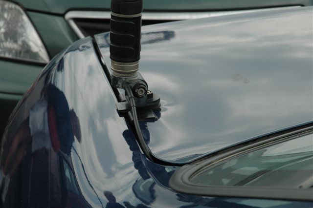
The damage to the trunk lid should in the left photo is obvious, but the damage to the quarter panel is less so. Repairing this type of damage isn't going to be inexpensive, especially if the trunk lid has to be replaced. But this isn't the only damage which can occur.
The antenna in question is a Yaesu ATAS120. From the get go, it is not a sturdy antenna in any respect. Each time the trunk lid is opened and closed, stress is placed not only on the mount, but on the antenna as well. What's more, trunk lip mounts allow the antenna to sway back and forth, further exacerbating the body damage, and the mechanical stress place on the antenna.
Another popular way to avoid drilling a hole is to use a mag mount. However, there are a couple of hidden problems with them. First, there is no RF ground connection. As a result, the coax cable radiates a large percentage of the radiated power (via common mode currents flow), and its pattern includes the interior of the vehicle it is mounted on! The other is the fact they collect road debris, typically metallic particles from brake shoes. Add in a little acid rain, and they leave circular patterns in the paint often referred to as mooning. Regular cleaning doesn't help either, and after a few months use, the moons standout like a sore thumb.
Here is something to consider. Rather than base your no-holes installation on trite references, base it on sound engineering practices, with a mind set towards what if... And that what if should include safe operation, ease of requisite repair, and associated long-term costs.
☜Return☜
Conclusion
For some, it is easier to believe myth, than fact. If you're not one of them, and you want to have a better understanding of antennas, particularly HF mobile antennas, then the real key is to learn the theory behind them. The best way I know how to do that, is buy yourself an ARRL Handbook. Read it cover to cover 3 or 4 times, and enough will rub off that you'll know more than most licensed amateurs.
No comments:
Post a Comment