
2 Element Vertical Array for 160M and 80M by VK3PAPage 1
In this series vertical antenna principals were reviewed with an emphasis on the importance of ground conductivity. When I embarked on my project I wanted to erect two 40-meter stand-alone verticals spaced one-quarter wavelength apart, and feed them out of phase. With number one up and running – and working very well - I started thinking why go to the trouble of mounting number two? The guilty feelings every time I drove into the garage and saw the clone in its box finally drove me to action. I had to stay with the program – hopefully it would be worth the effort.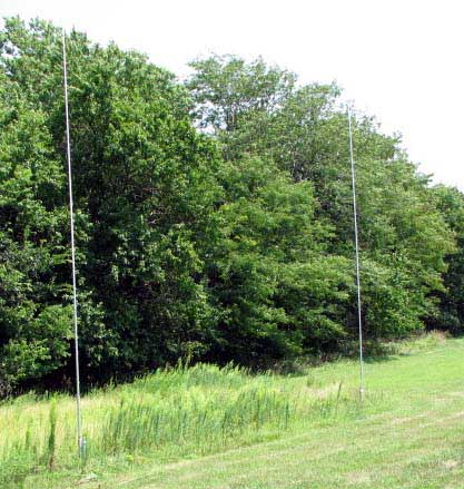
Before commencing any project one should have a goal in mind with an understanding of the dynamics involved. Reading up on the principles of multiple mono-band antennas seemed daunting, especially since I do not like looking at equations, complicated figures and graphs. It always strikes me that the experts that really know their stuff just have a hard time putting their ideas in simple terms. Just the same if you peruse through the fodder you can get the fundamentals, and this will allow you the knowledge to gain the most for your project.
Anytime you place two antennas that are resonate on the same frequencies close to each other you are going to experience mutual coupling. This can be very positive, as you will see. Most of us have heard someone talking about their “four square” or “end fired phased vertical arrays”, and marveled at how relatively strong the signals were. What is all of this chatter on the air about phasing and directivity, and how can this be done with verticals?
There are four main benefits of using two or more antennas – directivity, noise reduction, gain and rejection of unwanted QRM. Everyone wants gain, and noise reduction is of course universally appealing. Not true with rejection and directivity, as those rag chewer types just want to be able to talk away across 360 degrees of space. Triplet antennas with the center element fed differently then the other two might be their best bet. Such a three stack will emit a significant gain – upwards of 5db – with a broadside pattern. Just like having an amplifier. Figure 25 taken out of the ARRL Antenna Handbook2 shows a different version where the currents are fed in a binomial method with a ration of 1:2:1. The gain is about 5db and is bi-directional. The feed lines are ¾ wavelengths by necessity due to the ½ wavelength spacing. The advantages are that such a system is simple, does not require relays or phasing boxes at the feed points, and would be more or less maintenance free. The gain of over 5db is appealing too. However, you give up one of the more important objectives – backside QRM and directivity!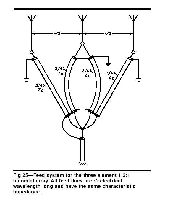
My objectives were different. I wanted gain, some directivity, and QRM rejection. I also sought a broadside option that would allow the rag chewer in me to have QSOs on an omni directional basis. Basically I wanted the whole enchilada. I knew enough to know this would require a setup that would provide a null in either direction, gain in the opposite direction, and would not be too complicated. At this conceptual stage trying to comprehend more then two antennas was too much for the complicated part, and the thought of laying out pounds and pounds of ground radials for three or four verticals was overwhelming. I needed to stay with a two-antenna project.
Lets have a look at how two mono-band siblings can be made to work with each other. When two verticals are lined up in a certain direction, and fed out of phase, they are referred to as “end fired” arrays. A good rule of thumb to remember is the array always fires in the direction of the element with the lagging feed current (this will clear up in a minute). By altering the phasing you can basically move them around to your design parameters to achieve the best performance for forward gain and unwanted backside rejection.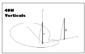
Think about a full wavelength of RF energy – a sine wave that travels 360 degrees at warp speed – your frequency. Visualize the waveform as it goes from zero to its most positive point and then back to negative territory as it heads south, and finally back up to zero. At one wavelength it has traveled 360 degrees – at over seven million times per second on 40 meters! At the 90-degree point it has advanced one-quarter of a cycle or ¼ of the full wavelength. If we put two identical verticals spaced 90 degrees (one quarter wavelength) from each other a receiving signal coming in line toward the direction of antenna one will arrive at antenna two 90 degrees later due to their physical separation. This assumes that the receiving signal is traveling horizontally, which is never the case as signals arrive at different angles – a fact we can ignore for the moment. If we want to cancel out the signal coming toward antenna one we can do this by making the feed line to antenna two “electrically” one-quarter wavelength (90 degrees) longer at the feed point. Now the two received signals will be 180 degrees out of phase, 90 degrees due to the physical separation, and an additional 90 degrees stretched out with the quarter wavelength phasing line. In this condition the two null each other out. Bingo – we just eliminated signals coming toward antenna one. Since signals are arriving at different angles on antenna one complete attenuation never happens. However, for all intents and purposes a lot of the signal can be effectively attenuated, especially QRM coming from the unwanted direction.
Just the reverse affect happens when the receiving signal arrives from the opposite direction, or in line with antenna two. This time the 90 degree phasing line on antenna two delays the signal to match its arrival on antenna one. Now the two received signals are in phase with each other and combine to enhance the result. The same principal works on your transmitted output with a 4db directional gain! Not a bad way to enhance your output while at the same time eliminating unwanted signal clutter from the opposite direction. By feeding both antennas without the phasing shift you have a broadside array for rag chewing.
It is easy to comprehend that phasing with a multi-band antenna would add a whole new set of problems and complications. Everything changes with frequency – the phasing line length, the feed point impedance, the physical separation etc. Not for me but maybe for the more adventuresome.
I started the project knowing that it would require solidly built and self-supporting sets of antennas. I decided to go with two 40-meter verticals manufactured by Zerofive-Antennas (www.zerofive-antennas.com ). My research showed this company offered the best quality in the market. The owner, Tom (N9ZV), builds each antenna by hand and you can feel and see the difference. The quality is superb. The base plate for attaching the radials was purchased from Lance Johnson Engineering (http://www.lancejohnsonengineering.com).
With number one up and running, number two was erected exactly one-quarter wavelength away lined up east and west. Since my home sits in the middle of the country this seemed the most logical alignment. Just like number one, antenna two needed radials so I had a lazy thought! Why not allow the “twins” to share? So I took six of the 24-quarter length radials laid out for one and hooked them up on number two’s base plate. This left only 18 new radials to be added. More, or course (Zerofive-Antennas recommends 60 –ugh!) would work better but the array is performing exceptionally well “as is”! I kind of figure I will add some at a later date, perhaps enough until the feed point resistance of each antenna stops declining.
If your ground conductivity is not very good you might consider raising both antennas about eight feet. This will allow you to install two elevated “tuned” radials cut to a quarter wavelength at the lowest operating frequency you plan on using – you may have to experiment trimming their length to get the feed point resistance right. You can slope them down about 40 degrees to get a better match for your phasing lines at the antenna feed points. Keep them about 180 degrees apart and isolated from the ground. This alternative will give you an excellent ground return without the hassle of ground-mounted radials! (Both the ARRL Antenna Handbook2 and ON4UN’s Low Band Dxing1 have excellent examples on elevated radial arrays.)
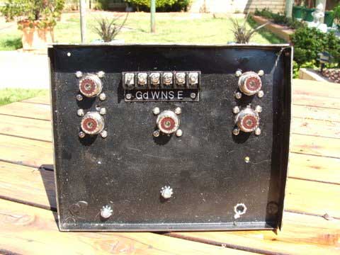
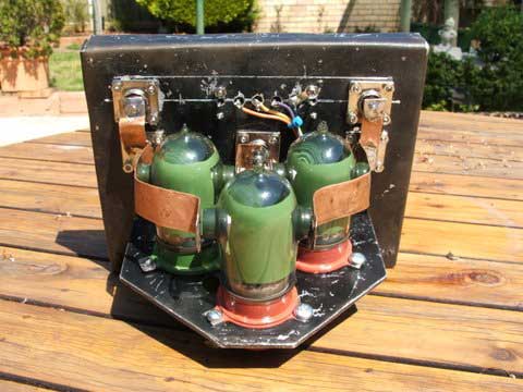
Since I have a demanding business my time is limited so I made the decision to use a commercial phasing device as opposed to a home brew setup. Comtek Systems PVS-2 model was the perfect solution for the phasing network as it is designed to work with a two-antenna setup. It is well built, will handle the full legal limit, and reasonably priced at about $350 delivered. They also supply the four-wire cable needed for the hookup at $0.26 per foot.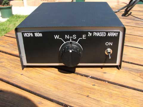
There were two very important requirements to make the system perform well. First, both antennas need to be resonating on the same frequency. Using my MFJ antenna analyzer I adjusted the height of each one so they were identical in frequency. The other condition was to feed each one with an exact one-quarter “electrical” wavelength piece of coax from the feed point or distribution box. Cutting the coax to the proper length is critical to insure the currents and voltages at the feed points are identical. While you can size the lengths based on the velocity factor of the coax (multiply the desired length by the velocity factor) this is not very accurate due to variations in the manufacturing process.
To achieve the exact electrical length I used my MFJ antenna analyzer by following their directions. Alternatively you can put together a SWR circuit using a dummy load, a coaxial T connection, and a SWR meter in line with your transmitter. Cut the first piece of coax to a physical one-quarter wavelength – this will be too long. Short the opposite end, and connect the other end to the T connection coming from the transmitter – the other side of the T connector will be feeding the dummy load. Using very low power with the transmitter start trimming the coax until the SWR reaches its lowest point at the desired frequency (the ARRL Antenna Handbook2 has a more complete description of the process). Do the same for the other feed line and they will have identical voltages and currents at the feed point! Without this condition you will not achieve the rejection when feeding the array out of phase.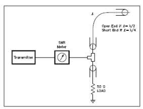
The only other addition needed for the Comtek Systems was a low-power dummy load at the distribution box. I found a 100-watt unit in my junk box, which works well even at legal limit power levels - only a small level of power dissipates through the system!
After getting everything hooked up I made a QSO back East with the array firing in that direction. I politely asked if it would be okay to switch directions to see how the backside would perform. My contact was astounded to note that I almost disappeared into the noise, and believed the attenuation to be around –25 to –30 db. Holy cow – this baby really works. Having used the antennas for some time with my PRO-II and home brew 600-watt amplifier I can honestly say this is my best antenna ever for 40 meters. Based on my estimates the forward gain is around 4db – just like having a booster on the amplifier. One other advantage of the Comtek system is the broadside setting which allows QSO’s on opposite sides of the array but minus the benefits of phasing - the whole enchilada!
If you are on a limited budget inserting a phasing line with relay controls and a matching network would not be difficult following the many examples in ON4UN’s Low-Band Dxin Manual. Don’t be afraid to “home brew” the antennas. Both references have many examples and you can get your feet wet on some of the more simple ones. I especially like Alan Christman’s (K3LC) feed system outlined in Chapter 11 of ON4UN’s1 book.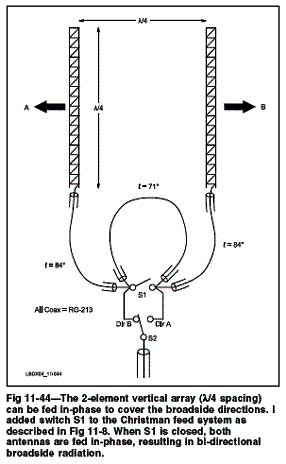
Note the difference in the phasing lines – a variation in design from the 90-degree model I used. Switching S1 allows a broadside signal to allow both direction QSOs, or S2 to give you directivity. You will almost always achieve the likely 4db gain but you may have trouble with rejection on the backside if the matching sections are not cut to the proper electrical lengths.
The variations for these types of phased arrays are endless. One thing seems clear to the amateur experimenter – there is no perfect “phased array”. When considering the many complexities and alternatives good reference books are ON4UN’s “Low-Band Dxing1 and the ARRL Antenna Handbook2. Build your own to whatever objectives you want and start enjoying consistently good signal reports!
ON4UN’s Low Band Dxing - ARRL Order No. 7040 (www.arrl.org/catalog)
The ARRL Antenna Book 21st edition (www.arrl.org/catalog)
Wednesday, May 22, 2013
2 Element Vertical Array for 160M and 80M
Subscribe to:
Post Comments (Atom)
No comments:
Post a Comment