

THE 80M ANTENNA
The current Antenna system in use here on 80M is a 3 Element, in line, phased vertical array.
LAYOUT
Constructed from wires, suspended from and in tall Oak trees, this antenna makes every effort at breaking all the published rules as far as the ideal construction of vertical antenna's is concerned. Trees unfortunately move in the wind, this leads to regular maintainance in order to maintain performance.
The Vertical's are aligned East, West, and are spaced at 0.18 wavelengths, this unusual spacing was dictated by the position of the Oak trees alone! Owing to the unusual spacing much simulation work with EZNEC was done to determine optimum phase of the drive current to each element. The final value selected was +/- 128 degrees with a standard binomial current distribution of 1-2-1 Amps. Owing to the relative position of the house and the Vertical elements, symmetry between all elements could not be achieved. This of course means that the back to front ratio of the array would be different for each direction. The fundamental reason for this is the position of the house, neither it or the closest element could be moved. Plumbing and wiring in the house does mutually couple into closest antenna and effect the drive point impedance. I just had to live with it! One other reason is the difference in ground loss, i.e. differing number and length of radials at each vertical. It was not possible to move the house and garage to plant radials!
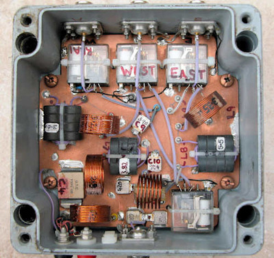
Photograph showing the phasing unit Layout of the 3 verticals EZNEC Plot of my 3 Element phased array with +/- 128 deg. feed
The plot above shows quite well why the 3 Elements in line configuration is so highly regarded. Although my arrangement is rather unconventionally spaced at about 0.17 Lambda back to front ratio is excellent at 25-30dB. In practice I have found that this can be achieved providing the element drive point impedance's are accurately calculated. This means careful measurement of the individual element self impedance's and mutual coupling between all vertical elements in the array. With this information the phasing arrangements can be designed with confidence.
I have written some Mathcad7™ files which do the complex number calculations and determine the driving point impedance's for a 3 element array. All that is needed as input, is the measurements of individual element self impedance and the effect of mutual impedance for each element due to coupling between elements in the array. Also required is the individual antenna current magnitude and phase. You will of course require, or have access to Mathcad7™ from MathSoft Inc. For most 3 Element arrays this will be a 1-2-1 (binomial) current distribution. There are 2 files in a "zip" for this, both are fundamental the same but with the phase of the outside elements reversed. One calculates beaming East, the other West. In a perfectly symmetrical array, where all elements have the same self,impedance and ground loss, calculations will be identical for either direction. In my case this is not so for the reasons explained earlier. 2 phasing networks are needed, one for each direction due to the dissimilar antenna feed impedance and spacing.
Download Mathcad7™ file to calculate Drive point and Mutual Impedance
FEED ARRANGEMENT
For a 3 Element array with 1-2-1 current distribution by far the best way to feed each antenna is to use the "current forcing" method described by W7EL. This makes use of the properties of quarter wave lines to provide the correct drive currents. The centre element is fed with 25 ohm coax and the outer elements are fed with 50 ohm, thus forcing double the current to the centre element. Additional phasing and matching to 50 ohms using L/C networks are used to provide the correct phase of drive current to each element. Phasing networks or "Line Stretchers" are a very necessary part of phased vertical designs. Line stretchers are designed around a fixed resistive characteristic impedance and any reactive part of the load impedance must be cancelled before commencing the line stretcher design. I have written a Mathcad7™ file called Line_stretcher.mcd which allows calculation of a "T" or "PI" network Phase Shift network for a given value of phase shift. All that is required for input is input/output phase, characteristic impedance and frequency.
Download Mathcad7™ file Line_Stretcher.mcd
In my case because of the lack of symmetry between the elements, 2 discrete phasing networks are used, 1 for each direction. This enables optimum back to front ratio in each direction despite the non symmetrical layout.
Using the "Current Forcing" method requires that voltage and impedance magnitude-phase information is known at the feed end of the quarter wave coaxial feed lines. This information is required to enable the design of a suitable phasing network and ensure that the correct current relationship in each vertical antenna element is maintained. I have written a Mathcad7™ file called COAX_Z.mcd that calculates the voltage, current and impedance parameters at the input to a quarter wave coaxial line for a given antenna driving point impedance and current. All that is required is to input the antenna drive point impedance, current and coaxial cable characteristic impedance.
Download Mathcad7™ file: COAX_Z.mcd
2 ELEMENT ARRAY
For simplicity the 2 element array spaced a quarter wave cannot be beaten. Try feeding it using the coax feed arrangement described by Al Christman KB8I in HAM Radio, May 1985 and also shown in ON4UN "Low Band DXing". This method is very simple and also clever. It relies on selecting the correct coax feed length so that the feeders can be joined together at a point where voltage magnitude and phase are the same. I have used this method with great success on an earlier incarnation of phased verticals for 80M.
CONCLUSION
Don't be put off by all you read about the perfection required for phased vertical arrays, agreed, perfection is best but second best can be good as well! Providing you realise where the imperfection lies, it is possible to engineer your way around many problems, especially if you are prepared to employ a more complicated phasing arrangement that is designed for just a single direction with another switched in for the opposite direction. There is no denying that a 120 radial system per antenna in the centre of a 10 acre open field is best but wires in trees give me a lot of fun!
I always think that the best testimonial is when a DX station asks "what antenna" or "what power are you running", inevitably this means you have a good signal. I have been asked this many times by US stations on 80M. My 3 element "in line" array is arranged to fire either East or West and was arranged this way to put a good signal into the USA for USCH. Where I lose out with this array is towards Japan and down to Africa. I could work many more JA stations with a single vertical when I had one, but that's life. The only way around this would be to errect a 4 Square to give 4 switchable directions, some day maybe! So far I have worked 839 US Counties and all States on 80M CW only, not an easy task from Europe but great fun. I am also now the holder the CQ USC 500 award number 3427 endorsed for 80M CW only. There is no denying, Vertical Phased arrays will never disappoint, they always seem to work much better than the sum of the individual parts that make them up! CU on 80M CW.

GOOD REFERENCE ARTICLES ON VERTICAL PHASED ARRAYS
Feeding phased arrays:An alternative method. AL Christman KB8I Ham Radio, May 1985. Excellent information on easy 2 Element phasing.
Phased Driven arrays for the Low Bands: AL Christman KB8I QST, May 1992
Vertical Phased Arrays: Forrest Gehrke, K2BT. Ham Radio, May, June, July, Oct, Dec 1983. Concludes in May 1984. (The definitive Article)
Low Band DXing by John Devoldere ON4UN. Useful software also available to help with all aspects of phased array design.
EZNEC. Excellent Antenna modelling software by Roy Lewallen W7EL.
No comments:
Post a Comment