Low cost fishing pole vertical antennas
Introduction
These antenna ideas are aimed at those who have limited space for antennas and want to make their own antenna using ordinary household tools, using parts that are easily obtained, and needing little in the way of test equipment.
The performance of these antennas can be every bit as good as a multi-band commercial vertical and at a fraction of the cost. In the case of the parallel wire version (without traps) the performance can exceed the commercial units.
These antennas are based on a 10 metre fibreglass fishing pole. It is important to use fibreglass poles, not carbon fibre. Fishing poles can be obtained from several sources, including eBay. They are also sold as flag poles of the type used to fly banners at camp sites. The more expensive "Spider Poles" can be used, however ordinary low cost poles are quite adequate.
Band Options
A ground mounted vertical will be less efficient than one mounted on a pole used with elevated radials. However, most of us will not want to clutter a small garden with radials at head height, so often opt to mount a vertical antenna at ground level. On 7 and 10 MHz the performance of a ground mounted vertical is good compared to a typical dipole at 10 Metres above ground and will generally out perform the dipole for DX, however on the higher frequency bands the performance compared to the above dipole drops off but may still work well when conditions are good.
Vertical antennas can also be made for use on 80m and 160m, however for better efficiency (and ease of adjustment) these are generally better used in an "inverted L" configuration with a horizontal top wire. A modest sized 160m vertical, as described below, will enable signal exchanges of 5 x 9 to be made with European stations from the UK on most evenings when running 100W or less.
There are several "easy" combinations which work well together for multi-band home made verticals, the examples shown here are a trap vertical for 7 and 10 MHz, a trap vertical for 7, 10, 18 and 24 MHz and a parallel wire vertical for 7, 10 and 14 MHz. Variations are of course possible, such as a parallel wire for 14 MHz added to the trap vertical. The four band vertical uses two parallel wires with a single trap in each wire, one trap is tuned for 10.1 MHz and the other for 24.9 MHz. Some bands are quite close in frequency and will limit the choice of frequencies used in an antenna, for example 24.9 MHz can clash with the 21 and 28 MHz bands. One possibility would be to use two antennas, one for 14/21/28 MHz and the other for the WARC bands of 10/18/24 MHz.
A 3 band elevated ground plane for 14/21/28 MHz can be easily made using a 21 MHz trap in a 14/21 wire with a parallel wire stood off by around 7 inches on fibreglass tubes for 28 MHz. I use this antenna for my station in Spain with the wires taped to a 7 metre fishing pole mounted on a roof balcony, with two radials per band. The fibreglass tubes are 6mm diameter and fixed with epoxy adhesive into 3 hole "modesty" plastic blocks of the type used to secure wooden panels, in turn these are securely fixed to the pole with Ty-raps.
Multiple traps can be used in a single wire with the vertical, however the performance will drop with every trap that is added. By limiting the number of traps to no more than one per wire, the performance is maximised.
Capacitors can be re-used and traps are easy and cheap to make, so feel free to experiment!
Materials, tools and test gear
The following items are needed depending on which version you make:
Fibreglass pole, wire (suggest 32/0.2 wire), roll of black PVC tape, 6 or 8mm fibreglass tube (or PVC 16mm oval electrical conduit and 12mm dowel), 40mm plastic waste pipe, 14 SWG (2.0mm), or 16 SWG (1.5mm) enamelled copper wire for trap construction or slightly thinner for loading coils, 25 pF 7.5 KV "door knob" capacitor, polypropylene garden twine or thin rope, fence post, guy stakes and cable ties.
14 SWG (2mm) wire is the largest practical diameter for winding coils on 40mm plastic tube, however the thinnest should not be much less than 16 SWG to keep trap loss to a minimum.
In addition to hand tools and a soldering iron, the following are also needed:
Hot melt glue gun (traps), dip oscillator (traps) and an antenna analyser or SWR bridge. Optionally, a low cost capacitance and inductance meter can be useful for checking capacitors and loading coils... The LC200A type of meter is easier to use for LC measurements than an antenna analyser.
You may also opt to make a feedline choke in a suitable box, the additional items needed are a coax socket (SO239), two terminal posts, ferrite ring (suggest FT240-31 or FT240-43 for higher bands, FT240-73 for 160m) and a short piece of RG58 coax (or the more expensive Teflon coax, RG142, for power levels up to 1.5 KW).
Door knob capacitors, fibreglass tubes, enamelled copper wire and ferrite rings can be obtained from eBay suppliers. Conduit and waste pipe came from local DIY stores. Spiderbeam supply 1 metre lengths of RG142.
Parallel wire vertical
To minimise interaction between the wires in a parallel wire vertical it is necessary to space the wires well apart. To allow for the pole flexing in the wind, at least 300mm spacing is suggested. Spacers can be made from 16mm wide oval electrical conduit or small diameter fibreglass tubing - 6mm or 8mm diameter is strong enough. By itself plastic conduit is quite weak, to strengthen the point where the spacers are fixed to the pole it is necessary to add wooden dowels. These only need to be around 120 mm in length by 12 mm or so in diameter, and can either be used to join two lengths of conduit "back to back" or pushed into the conduit from one end. I used 480mm lengths of conduit joined "back to back" plus the single 480mm length for a top support. To lessen the visual impact of the antenna, I covered the white conduit with ordinary black PVC insulating tape. The spacers are fixed to the pole with a pair of cable ties.
The wire lengths are calculated from the formula L = 234/F, where F is the frequency in MHz and L is the wire length in feet. These lengths work out to around 33' 3", 23' 2" and 16' 7" for the 7, 10 and 14 MHz bands. The lengths are generally shorter in practice than the formula suggests which is just as well as otherwise the pole wouldn't be long enough! However probably due to interaction between the wires, the 14 MHz wire needed to be around 4" longer than calculated. Wire size is not critical, but it is probably better to avoid the thinnest "hookup" wire, I use 32/0.2 wire. Note, ground conductivity/loss and elevated/buried radials make a significant impact on both the performance and tuning of a ground mounted vertical.
Start with a single wire for the lowest band (longest wire), tape it to the fishing pole in a spiral fashion, ensuring each joint in the pole is taped to avoid it collapsing, then fold the end of the wire for minimum SWR, add the next band up and trim/fold, finally add the highest band and trim/fold. There will be some interaction, so it is better to fold the ends rather than cut and have to add an extra length of wire.
Trapped vertical
Instead of using parallel wires, home made traps can be used. Commercial trapped antennas are very popular, can be expensive and often perform poorly. While traps appear to offer the advantage of multi-band operation on a single vertical pole, the disadvantage is they shorten the antenna, which in turn lowers the feed impedance and reduces the bandwidth. There will also be some loss associated with each trap, however it should be less than 1 dB. The overall height of the 7 and 10 MHz trap vertical shown here is approx 26 feet, the top two sections of the fishing pole are not used (the open tip is taped to keep rain out).
Trap construction
The 7 and 10 MHz dual band trap vertical needs a 10.1 MHz trap. The trap shown below comprises 18 turns of 16 SWG enamelled copper wire wound on a 40mm diameter plastic pipe offcut which had been wound with black PVC tape to minimise the visual impact. A 25 pF 7.5 KV "door knob" capacitor is placed inside the coil and soldered in parallel with it. Start with 20 turns of wire and remove a turn at a time until the trap resonates at 10.1 MHz using a grid dip oscillator. Stretch or squeeze the coil until the dip oscillator shows a resonance in mid band, this is with the coil and capacitor on their own, i.e. without wires attached to the ends. Check the calibration of the dip oscillator against a receiver, when you are satisfied the trap is set where you want it, secure the coil with hot melt glue. A plastic disc was glued on the top of the trap to keep rain out. The exact value of the capacitor is not critical, as the capacitors are mostly surplus the choice can be limited to the value you can source. 50pF capacitors with fewer turns on the coil could be used. Avoid wire ended capacitors, even if they have the Voltage rating, as they will not handle the current. The type of capacitor I used is shown below.
If you want to make a 24.9 MHz trap, try 7 turns of 14 SWG on a 40mm former with a 25 pF capacitor. The trap shown below right, has been secured to a PVC stand-off arm with hot melt glue - which adheres well to this type of plastic.
Note: Various articles mention the need to avoid a trap being resonant on the band you are using it for. This is quoted as being necessary to reduce losses and to reduce the peak Voltage across the trap. When a trap is tuned "on it's own" the resonant frequency will be reduced when used in an antenna, for example the resonant frequency of a trap tuned for 24.9 MHz was reduced to 21.5 MHz in this antenna.
While it is possible to use traps made from coaxial cable, coil and capacitor traps have less loss and greater power handling. A previous trap made from RG58 coax exhibited SWR creep at power levels between 200 and 300 Watts.
There is no need for additional weather coating on the traps, rain doesn't alter the performance as far as my SWR indication shows.
Power handling
The above traps have been tested at the UK limit of 400 Watts with no sign of SWR change or any other unwanted issue. Traps made from 7.5 KV "door knob" capacitors should be good for 1 KW output and probably more. Higher Voltage capacitors are available, but tend to be large and heavy.
Wire cutting and antenna tuning (trap vertical)
Unlike the parallel wire vertical, with the trap vertical start with the highest band (shortest wire) and fold/ trim the wire for optimum match, then solder the trap onto the wire and add 5 or 6 foot of wire at the tip. Check the higher band still has a good match, then fold/trim the wire from the tip for the lower band.
If you want to try a dual wire, dual trap antenna, for 24/18 MHz (one wire) and 10/7 MHz (the other wire) the order of assembly is as follows:
Cut/trim the 10 MHz wire, add the 10 MHz trap, then add the tip wire and trim for 7 MHz. Then add and trim a parallel wire for 24.9 MHz, finally add the 24.9 MHz trap and trim the associated tip wire for 18 MHz. This combination works quite well, although my minimum SWR on 18 MHz is around 1.7:1.
Verticals for 80m and 160m
Loaded verticals for 160m and 80m have been popular for a number of years and are easily made. In order to give maximum efficiency the loading coil is usually mounted near the top of a vertical pole with a horizontal wire running from the coil. Several combinations of vertical and horizontal wires are possible, examples for 160m include a 25 foot vertical wire, 64 uH coil and 45 foot of horizontal wire or a 132 uH coil and 25 foot horizontal wire. While it makes calculating the length of wires difficult, using 3 or 4 wires in the form of "spokes" from the top of the coil will improve performance over a single wire. A 40 foot vertical with 4 x 50 foot wires from the top of the vertical will resonate on 160m without needing a loading coil, however that spread of wire is not practical in many modern garden sized plots.
As the bandwidth of loaded antennas is very narrow, especially one for 160m, any change to the value to the value of the coil or movement of the pole will impact on the resonant point. Try to use as large a diameter of enamelled copper wire in the coil as practical (to minimise heating) and also try to keep the antenna away from other antennas and metalwork.
Similar arrangements to the suggested dimensions for 160m can also be calculated for 80m, although a full quarter wave "L" (without needing a loading coil) is not too large to install in many gardens. Tip... use a long enough horizontal wire to allow it to be lowered to within your reach by using a cord and pulley, it is much easier than lowering the fishing pole each time you want to move to a different part of the band.
Calculating the dimensions for 80/160m
There are several "on line" calculators for short wire antenna dimensions and loading coils, one example being the University of Edinburgh one. On the page there is a link to a coil winding calculator too. I have an inductance meter which is handy for checking coils, but for all practical purposes a loading coil need not be an exact value as the antenna will be tuned by adjusting the top wire.
Matching a 160m (or 80m) loaded vertical
Unlike the case of the higher frequency verticals, where the feed impedance is usually not far removed from 50 Ohms and a reasonable match easily obtained, when you use a loaded vertical for 160m the feed impedance should be much lower than 50 Ohms, how much lower depends on how many radials are used. In my case, with less than ideal radials, the feed impedance of a 25 foot + 25 foot "inverted L" 160m antenna was 21 Ohms.
In order to match the 21 Ohm feed to 50 Ohm coax a choke of approximately 3 uH was added across the feed point (lower end of the vertical wire to the radial connection point). The method of tuning is fairly straightforward if you use an antenna analyser. The 3 uH choke was made by wrapping 7 turns of 2mm enamelled copper wire around an aerosol can to form an open coil of roughly 80mm diameter that could be compressed/tuned with Ty-raps (the can is not used as a coil former only as a means of winding an air cored coil...), the value varied between approximately 1.5 uH and 4 uH depending on how compressed the coil was. There is an image of the coil lower down the page. For 80m a matching coil of half that size should suffice.
To adjust the matching coil, firstly you will need to adjust the top section of the loaded antenna without the matching coil in place. Connect the antenna analyser directly at the feed point, using as short a coax cable as possible, then adjust the antenna top wire until the reactance (X) is as near zero as you can manage at the frequency you want the antenna to operate on. Note X = 0 is the resonant point, which may not be where minimum SWR occurs. At this stage the SWR will be quite high, around 2.5:1 being typical. The resistive component (R) displayed on the analyser will probably be around 20.
Leaving the analyser set to the resonant frequency add the coil across the feed point and squeeze the coil until the resistive component equals 50, the SWR should drop significantly as you reach R=50. Tighten the Ty-raps to secure the coil at that matching point.
Note, the bandwidth of a short vertical on 160m will be very narrow, as narrow as +/- 10 KHz for a 2:1 SWR is likely with a 25 foot plus 25 foot antenna.
Mounting
The pole is fixed to a square section wooden post with re-usable cable ties (Ty-Raps) and will self support. Beware that most of the DIY grade cable ties may not be strong enough to use for this purpose. For windy locations guy lines can be added. These need not be elaborate, polypropylene garden twine secured to plastic tent pegs is good enough in all but the strongest of wind. Check the guy lines are strong enough, some plastic garden twine is so weak it can be easily broken by hand.
Radials
Like all ground mounted quarter wave verticals this one needs radials, the more the better. I currently have 16 random length radials cut into the lawn which return to an earth rod set into an old plant pot. The pot has a sandstone paving slab covering it. Buried radials can use any low cost wire, some of the less popular colours can sometimes be obtained at bargain prices. My radials use PVC insulated 32/0.2 wire soldered to a wire ring made from the same wire. The insulation isn't of course needed for buried radials. Buried radials do not need to be a 1/4 wavelength long as the soil de-tunes them, radials two thirds of the length of an elevated radial are optimum when buried 2 or 3 inches down in soil (22 feet as opposed to 33 feet on 7 MHz), however if you can't install radials of that length, put as many down as you can manage at whatever length fits.
Feedline
The antenna is fed with RG213 coax via a plastic junction box. The junction box includes a ferrite ring choke to minimise currents on the outer braid of the coax. The choke is made using 8 turns of RG58 (or RG142 for QRO) coax on an FT240-43 ferrite ring (or FT240-73 for the lower bands).
Frequently asked questions - Click here, opens in a new window
Results
The parallel wire vertical has a good SWR on all three bands with a minimum around 1.2:1. The dual band trapped vertical has a minimum SWR of approx 1.3:1 rising to 1.6:1 at the band edges. The four band (two parallel wires, one trap in each) gives similar results except the 18 MHz band has a minimum SWR around 1.7:1, the 160m antenna gives a perfect match at resonance, but is very narrow bandwidth.
On air results are much as you would expect from a ground mounted vertical. On 7 MHz the vertical is generally 2 or 3 S-units better than a dipole with it's apex at 30 feet for DX stations and often stronger into Europe as well. On 10 MHz the difference is less but the above generally applies. On 14 MHz the antenna is worse by 2 or 3 S-units on many EU signals however DX is usually better with the vertical. A 25ft vertical with 25ft horizontal wire and 132 uH loading coil gives S9 signals across Europe after dark while running up to 100 Watts.
DX worked in March 2006, running 60 Watts of CW, include:
7 MHz 4X4, 3B8, 5R8, 5H1, 9M2, 9M6, FS, A45, VR2, VY2, VK, ZL, BV4, J88 and SU
10 MHz 6W6, XU7, P40 and ZF2
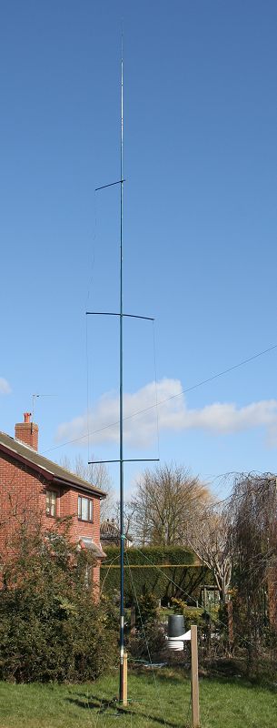
Parallel wire vertical
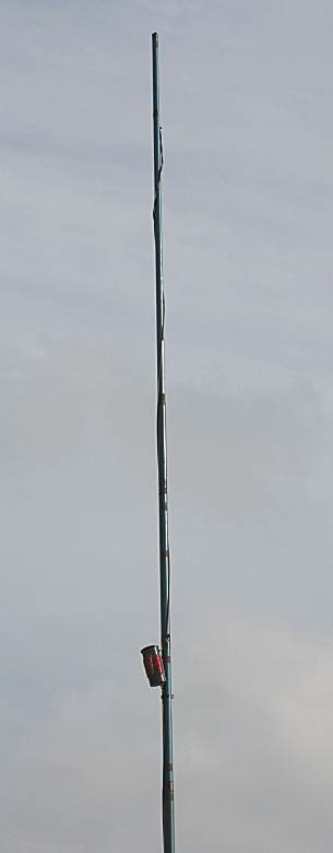
10 MHz trap in 7/10 MHz vertical
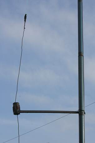
24.9 MHz trap in 24/18 MHz parallel wire
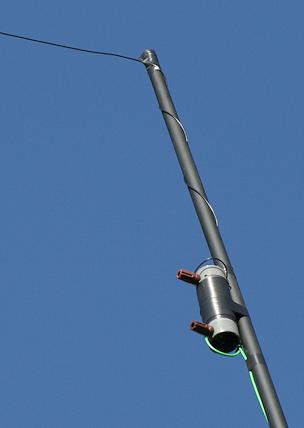
160m loading coil
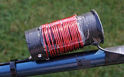
10 MHz trap using 16 SWG wire

"Door knob" capacitor
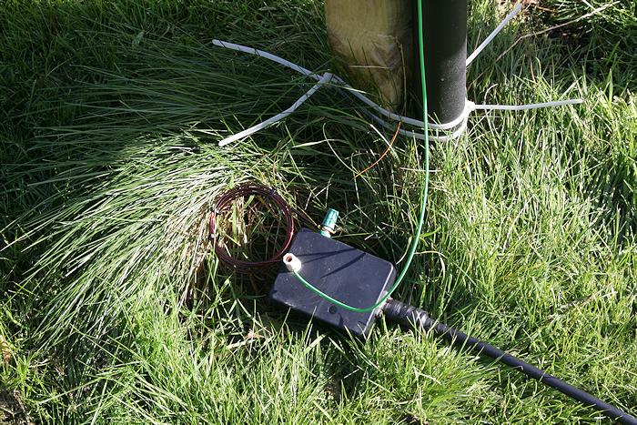
Feed arrangement showing 160m matching coil (remove the coil for use on 40m and higher bands)

No comments:
Post a Comment