
A C-Pole Antenna for QRPxpeditions
I've finished yet one more version of my Crappie Pole antenna, this one based on KF2YN's ground

independent vertical antenna (or C-Pole). See here and April 2004 QST, page 37, for more information. After trimming it a little it measures 1:1 at 14.060 MHz rising to 2.5:1 at 14.35MHz and 1.2:1 at 14.0MHz.
I found the choke balun to be key to making this antenna work. With no choke the SWR was over 14:1 at 14.060MHz and with a 10 ferrite bead choke the SWR was still 2.8:1 at 14.060MHz. What I'm using now is 15 turns of RG8X single layer wound on a 4" plastic coffee can.

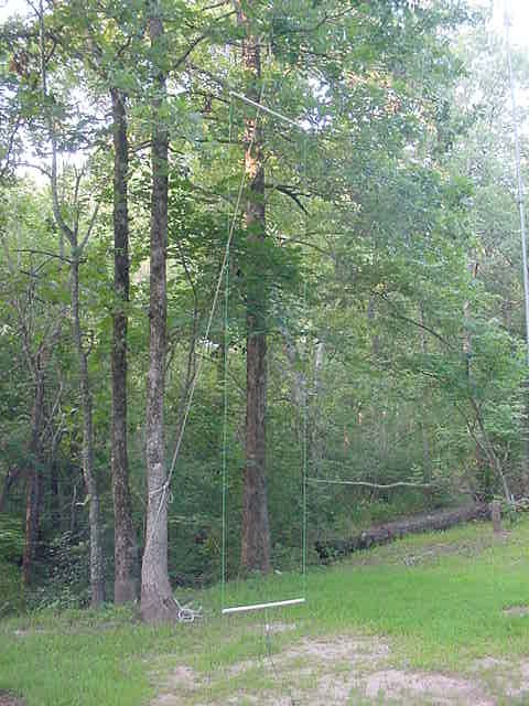
This antenna is about 18' tall, self supporting without guys and has only a 4' x 5' footprint. It breaks down to a bundle 5' long. Physically it looks like a tall skinny goal post. Add a birdie and two racquets and it should fit well into a typical camping weekend.
View a video of me setting up this antenna athttp://www.youtube.com/watch?v=nYn-GnwcSoE

Today I made several nice contacts using my K1 at 5 watts and this antenna including W8CQU in Ohio (599), WA3SLN in Pennsylvania (449), W0WCA in Colorado (449), KI0II in Colorado (549) and N4ESS in Florida (579).
This antenna is going with us when we go camping this summer. Thank you KF2YN.
Update: On June 23 I worked EA6UN on the Balearic Islands off the coast of Spain in the western Mediterranean Sea. That's over 4600 miles on my five watts and this antenna. I found Jurek calling CQ on 14.050 MHz with no responses. He came right back to me and gave a 579 report.
A Two C-Pole Steerable Array


Yesterday I finally got my two C-Pole phased array up and on the air. In fact, after tuning it a little I easily made two QRP contacts, one with N2UGB in NY and the other with CT4RL/1 in Portugal.
My journey from idea to an antenna was based on Chapter 13.3, "A Steerable C-Pole Array" in Brian Cake's book, "Antenna Designer's Notebook". Here Brian presented a design based on phased array theory and modeling. Brian was not aware of anyone that had actually built one.
The C-Poles themselves are made from Radio Shack 18 gauge stranded hookup wire. 1/2" PVC pipe is used for the top and bottom 40" spreaders. For easy supporting, the two C-Poles are in the same plane and aligned with the rope joining the two antennas. The upper inside corners of the antennas are connected by a 33.5' length of rope. This insures correct spacing. Support ropes are tied to the two top outside corners. Instead of a relay I used a coax T connector. L3 was added/removed as needed to change the radiation pattern.
Without L3 the array is endfire and, according to Brian's modeling, good for 1.18dBi gain. By adding L3 into the short/L2 side both sides become 3/4 wavelength long and the array has 3.5 dBi gain broadside.
I learned a little along the way about...
Baluns and phasing lines...The phasing lengths include the phase delay introduced by the required choke baluns. I had planned to use air core baluns consisting of RG-8X wound around 4" plastic coffee "cans". What I found was that each balun takes about 1/4 wavelength (electrically) of coax. By the time I added the baluns to L1 and L2 in the accompanying diagram I couldn't separate the antenna by a physical half wave. I was forced to use more expensive ferrite toroid baluns that require less coax.
Adding/removing L3...The switch/relay proposed by Brian in his design introduced its own challenges. The relay/switch is part of the phasing network. I found that my DPDT toggle switch with the needed connectors introduced more phase delay to the point that I was again in trouble with the physical separation of the two antennas. I eventually used a T connector instead.
Supports...Finding trees with the right separation, orientation, height and limb placement can be a problem...especially for a temporary installation in the park.
Measuring the electrical length of coax...My MFJ Antenna Analyzer gave a broad X=0 reading. My grip dip meter gave a sharp dip but not on the same frequency as the MFJ (The ARRL Antenna Book recommends against using a dip meter). Eventually I averaged the two MFJ endpoint/X=0 readings to get a center/single frequency and then calculated the coax electrical length based on that frequency.
Gain...1 to 3.5 dBi of gain is hard to notice when asking for signal strength comparisons under real band conditions.
This antenna array may be a good alternative for someone with properly located supports but my typical picnic table operating style doesn't always allow that. This was as interesting exercise but I'll probably keep using my single C-Pole when I'm at the park.
More C-Pole Vertical Array
After building/using my two C-Pole array I'm starting to rethink my plan.
KF2YN's C-Pole vertical array design calls for dedicated C-Poles (each pruned to have a 25 ohm input impedance) and phasing lines that both transform the antenna impedance to 100 ohms and set the phase delay between the two antennas. On the surface this looks doable but I've a lot of concern about getting the phasing lines right. W8WWV's measurements showed about a 4% delta as he measured the electrical length of a 17.1' long piece of coax. Also, I don't want to dedicate two C-Poles to an antenna that I won't be using much.
A local friend of mine wants to build a self supporting C-Pole antenna like mine. I can feed two verticals with arbitrary (but equal) lengths of coax and a simple Tee connector at the antenna tuner to make up for the 25 ohm combined feed impedance...no need to worry about electrical lengths. In addition, self supporting antennas can be positioned anywhere to point my signal where I want it to go that day. I can even boost the gain a little (up to 4.8 dB) by separating the antennas 5/8 wavelength.
It's still August, I should have another couple of months of outside weather here in Minnesota.
Phased C-Pole Antennas for some Gain
How many times have we seen 18 wheelers with CB verticals mounted on their mirrors? Doing this, truckers add a little gain on 11 mtrs. With proper spacing this works even better on 20 meters.
Today was a sunny day here in SE MN. The temperature was in the low 70s and there was no sign of rain. It was a great day to meet Rodney, KD0EBT, and Steve, KD0ORM, for a little KX3 time at Rochester's Essex Park. My August 23, 2010 blog post proposing that two C-Poles be fed in phase is based on information in the ARRL Antenna Handbook. Information there states that two verticals fed in phase and spaced 5/8 wavelengths apart exhibit almost 5dB gain over a single vertical. My experiments today seem to confirm this information.
I already have one self supporting 20 mtr C-Pole antenna. I built a second 20 mtr C-Pole. This one hangs from a tree limb like W5USJ 's. A little searching around Essex Pack identified a tree with some open space to the south. I merely hung one C-Pole in that tree and set my self supporting C-Pole about 44' (5/8 wavelength on 14.1 MHz) to the south. This put the two broadside to the east/west. I fed each of the antennas with 50' lengths of LMR-400 low loss coax. At the rig I had a short coax jumper to a tee, connecting my KX3 to both antennas. I let the KX3 internal turner take care of any mismatch caused by driving the two 50 ohm C-Poles in parallel. Measurements using the Reverse Beacon Network showed that these two C-Poles fed in phase and spaced 5/8 wavelength apart really can have 5 dB gain over a single C-Pole.
Now I've another portable antenna option for those days in the park.


A Choke Balun for Phased C-Poles

It is important that the baluns used in a phased verticals match, otherwise the phasing, beam pattern and gain won't be as planned. They also must handle the high common mode potential at the feedpoint. KF2YN shows two different balun designs in his April 2004 article. One is just multiple turns of

coax wound around a piece of PVC pipe while the second uses a ferrite core. The ferrite core design, while more expensive, also has much less power loss. For my phased verticals I chose Brian's toroid design. It

uses 19 turns of RG-174/U coax wound on a FT-240-67 core. I mounted mine in plastic electrical boxes with an eye-bolt to allow hanging from the bottom C-Pole 40" spacer. This balun does no impedance transformation. The balun coax is simply in series with the antenna feedline.
No comments:
Post a Comment