Saturday, June 30, 2012

TAK spiral antenna

TAK spiral antenna


Introduction And Conclusions top

An experimental antenna similar to the TAK spiral antenna was evaluated for SWR response
over the frequency range of 7.0 to 7.3 MHz, or the 40-meter band.

Summary of results

  1. Beam length has a significant effect on SWR response. Increasing the distance
    between spirals increases the antenna's resonant frequency. Beam length can be used
    to fine-tune a spiral antenna to the desired resonant frequency.
  2. The combined length of antenna and hookup wire has a significant
    effect on the antenna's resonant frequency. The longer the combination, the lower the
    resonant frequency.
  3. The diameter of a spiral antenna affects its bandwidth, as measured by the frequency
    range where the SWR is equal to or less than a value of 2. Increasing spiral diameter
    increases bandwidth.
Background top

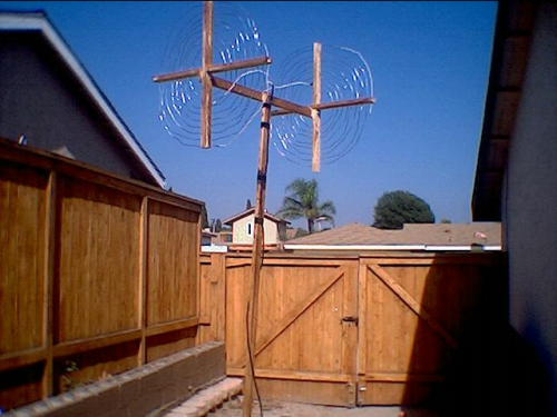
TAK markets and sells a 40-meter antenna that is a unique arrangement of a simple dipole
where the quarter wave sections are wound into flat spirals instead of being arranged in
a straight line. The advantage of this configuration lies mainly in its compact size. The
finished antenna easily fits into a 3-foot cube.


TAK Antenna

George Mann, the president of the Lakeland Radio Amateurs Club was kind enough to let me
study his TAK antenna. For this experiment the TAK's major drawback was its fixed length
beam. An easy to construct design that overcame this shortcoming was needed.

Materials used to construct an adjustable length beam antenna are available at any home
center and consist mainly of PVC electrical conduit, and two sizes of PVC water pipe.
Fourteen-gauge aluminum wire was chosen for the antenna because of its low cost.

Design and Construction Of An Adjustable Beam Spiral Antenna top

Construction consisted mainly in cutting PVC to length and drilling holes. A modified spade
bit, ground to the diameter of the gray PVC conduit used for the cross arms, was used to
drill holes in the movable sections of the beam. To insure that the holes were at right
angles to each other, a simple jig was used to hold the beam member during the drilling
operation.


Drilling Jig

The image above shows the jig in use during the drilling operation. After the first pair
of through-holes are drilled, a piece of scrap PVC is inserted through these holes, and
the piece is then returned to the jig with the scrap PVC now resting on the locating rails.
This insures that the next pair of holes in the PVC will be at right angles to the first pair.


One Of Two End Sections

In the above photo, the larger diameter PVC has been drilled and the spiral arms inserted.

The two cross members are secured with a single self-tapping screw.


Arm Attachment


Adjustable Beam Length

In contrast with the TAK, the beam in this design is not one but three pieces. Two hold
the spiral supporting arms, while the third, smaller in diameter section, fits into the
other two. This arrangement produces an adjustable beam. The above image shows how one
section slides over the other, in trombone fashion, allowing for the beam length to be
varied.

Spiral Antenna Design top

The primary spiral antenna design parameters are: the desired resonant frequency, the
length of the hook up wire that connect the antenna to the coax, and the minimum distance
the antenna wire is allowed to come to the end of any one PVC support arms. Once these
parameters have been determined, many spiral designs are possible by varying the spiral
pitch, or distance between turns, and the starting distance from the hub of the spiral.

From a mechanical perspective the most important design consideration is how close the
outermost end of the antenna wire comes to its supporting spoke. An antenna wire that is
an inch too short will leave a large section of antenna wire unsupported, whereas one
that is an inch or two longer than needed to reach the last support is easily tolerated,
and may even be an advantage in subsequent tuning. Therefore, it is important to choose
pitch and start values with this in mind.

Calculating the effects of starting distance and pitch on a known length of wire can be
tedious, and finding the combination that satisfies the condition that the wire reach the
last spoke with little or no overhang can be daunting. To address these concerns a spiral
antenna spreadsheet model was created to do the calculations for the designer.

For clarity the spreadsheet begins with a graphic showing the spiral antenna's most important
parameters which are: start point, pitch, safe edge, spoke length, and arm length.


A table of inputs and outputs follows the diagram. Inputs are in peach, outputs are in
yellow colored cells. The designer enters the desired frequency, the length of hookup
wire, assumed velocity factor, and safe edge. In response, the spreadsheet calculates
the required length of antenna wire in both inches as well as feet and inches. The
spreadsheet does its calculations in inches, but the user will find the conversion to
feet and inches more practical when cutting wire to length.

Of the remaining two boxes, one is labeled pitch, or the distance between turns, and the
other is labeled start, or the distance from the hub to the point on spoke R1 where the
antenna will start. Adjacent to these two inputs are two outputs labeled turns and min
spoke. The significance of turns is that values ending in 0, .25, .5, or .75 signify that
the end of the outermost lap of wire just reaches a spoke. A value not ending in one of
the above fractions means that the antenna wire will end between spokes. As mentioned
above, a little over is much more desirable than a little under.

Minimum spoke determines the overall size of the antenna. In fact the diameter of the
antenna will be twice this value. The length of the cross arms will be twice the sum of
the min spoke plus the safe edge.


The overall antenna diameter is calculated as values for pitch and start are entered. The
same is true for the overall arm length, the measurement needed to cut the support arms to
proper length.

Kerfs, or saw cuts made in the PVC support arms, in combination with plastic wire-ties,
are used retain the antenna wire. The spreadsheet creates a kerf cutting table based on
the pitch and start values entered. In practice two cross arms are placed at right angles
to each other forming a plus sign. Then in either clockwise or counter clockwise fashion,
spokes are labeled R1 through R4. The center is marked on each arm, and the table values
are then transfered to each spoke, starting at the center of each arm and working out to
the end.

The Effect Of Beam Length On SWR top

(Note: all SWR measurements were made using the MFJ Model xxx antenna analyzer. In each
case the test antenna was raised thirteen feet above the ground and connected to the
analyzer through approximately 60 feet of RG8 mini coax.)

The following graph shows the result of beam length on SWR. It is clear from these data
that as the beam is lengthened, or the spirals are moved farther apart, the resonant
frequency is increased. In this experiment the separation was varied from 27 to 37 inches in
two-inch increments. Over this distance the resonant frequency shifted approximately .18 MHz
or just over half the 40-meter bandwidth.


SWR vs Separation

The Effect of Spiral Diameter On Bandwidth top

Spiral diameter has an effect on bandwidth. Two antennas were compared, one with a 32-inch
diameter spiral, and another with a 48-inch diameter spiral. Tracing along the line equal
to an SWR of 2 the bandwidths of each variation can be compared. In this experiment the
frequency range at or below an SWR of 2 was much greater for the 48-inch model than for
the 32-inch model. The two horizontal lines at the bottom of the chart represent this
difference and are equal in length to the bandwidths of the 32 and 48-inch antennas
respectively. See figure below.


Comparison of 32 vs. 48-Inch Arm Length

Model Verification - Does the model work? top

A model is only as good as the results it produces. To test the validity of the spiral
antenna model an antenna was constructed according to the following parameters. See
table below. After selecting the resonant frequency, hookup wire length, and velocity factor,
pitch and start values were varied to produce an antenna with a slight overhang past its
last supporting point. This is one of many configurations that could have been selected.


The exact length predicted by the model was marked on a length of 14-gauge aluminum wire.
The wire was then cut a few inches longer than required. Next, two spirals were wound
according to the table above. The model predicts that there will be 6.06 revolutions. The
additional .06 revolutions amounts to 21.6 degrees and equates to an approximate distance
along the outermost lap of this spiral design of 5.8 inches. The average overhang for both
test spirals was just over an inch less than the theoretical value. This discrepancy can
easily be accounted for by construction technique.

After attaching the spirals to a beam, a series of SWR tests were made. In each case the
antenna was connected to 60 foot of RG8 mini and elevated 13 feet above the ground. The
antenna wire length was intentionally set long to insure that it would not be necessary
to add extra wire in the tuning process. Consequently, initial SWR measurements suggested
that the resonance point was low. Material was removed from the outer lap of each spiral
until the exact length of antenna wire determined by the model was reached. At that
condition the resonant frequency was 7.075 MHz. The aim was 7.15MHz. After two additional
inches of antenna wire were removed from the outermost lap of each spiral, the resonant
frequency increased to 7.096 MHz. Beam length was then increased by 4 inches to arrive
at a final spiral separation of 28.75 inches. This brought the resonant frequency to 7.17 MHz,
slightly above aim and favoring the voice portion of the 40-meter band.

The following graphic shows the SWR response as a function of frequency before and after
the final length adjustment. After adjustment, the SWR vs. Frequency curve can be seen to
shift to the right.


Extending the beam shifts the curve to the right.

Summary top 

The spiral antenna spreadsheet model accurately predicts the number of revolutions expected
for a given antenna length, pitch, and starting distance from the center of the spiral.

The spiral spreadsheet model has proved to be a useful tool for designing and building spiral
antennas for the 40-meter band.

Future Work top

There are many possibilities for future investigation. Some suggestions are:
  • The effect of wire gauge on SWR and bandwidth.
  • Directional properties of the spiral antenna.
  • The inclusion of a calculator within this web page

Read more...

Bill's- HomeBrewed TAK-tenna

Bill's- HomeBrewed - 40 Meter TAK-tenna or TAK Antenna


Project Overview:

So I've been reading about this Small Space antenna (Small Space HF Antenna) that is being sold as the TAK-Tenna. Really neat idea - Has a 30 inch boom and Spiral Coils on the ends. See a picture at http://www.taktenna.com/

Looks easy to build - Right ?

So I Built my version out of wood - Mine is very ugly as compared to the store bought one (See Pictures).

Materials and Tools • Parts:

1.)    3 - Wooden sections - 1 1/2 in X 1/2 in X 8 ft - Cost 92 Cents each - Home Depot

2.)    1 - 100' Spool of Steel Guide/fence Wire - Cost - $7 - Home Depot - The purchased version uses some type of "Special" patented wire, but this seemed fine.     I tried Copper, but it was not stiff enough to make the Spiral Coils.    Again from quick test it did not seem critical - From what I read larger gauge wire is better for improved band width.

3.)    1 - 25 foot RG8 coax with PL259 - Radio Shack - Close Out - $5

4.)     2 - Packages - Nuts/Bolts - $2 - Home Depot

5.)      2 - Aligator Clips - Free from my junk Box.

6.)      Few Feet of Electrical Tape - Free from my junk Box.

Total Material Cost: $16.76

The commercial version uses PVC and tie wraps, which would have been much easier.


Tools:

a.) Saw - I just used a simple hand saw.

b.) Drill with wood bits - I just used a simple hand electric drill.

c.)  Flat Screw Driver and Rubber Malet.

d.)  Wire Cutters.

e.)  Gloves and Eye Protection.

Fab Time:

For my version was about 4 hours - Drilling Lots of Holes and feeding the wire in to make the Spiral Coils was most of the work.

Testing:

However - Test wise it isn't bad I got it tuned up on 40 meters at about 8 feet off the ground and it has an SWR 1:2 to 1:5 from 7.30 to 7.175 MHZ (Without a Transmatch). Also does ok on 15 meter - Tune up wise. Bad news the performance is not Great - Signal pick up is several S units below my Dipole, but it does work. From what I have read the Antenna has problems in that most of the performance is based on feedline radiation (See the links below).

http://groups.google.ie/group/rec.radio.amateur.antenna/browse_thread/thread/167fb7a34305cf3e

http://lists.contesting.com/_antennaware/2008-04/msg00021.html

Summary of Results:

I'm still testing and it was an interesting experiment. The Antenna fits into a small space 25 inch X 30 inch. Hey it works. If you have no space it might be worth $20 and a few hours of your time or If you aren't a Homebrewer Buy one. If you make your own one point - I needed more wire than the 468/7.2 MHZ = 65 Feet Total or 32.5 Feet per side - I had to add wire after the fact. So I would make it about 33.5 per side.

Measurements:

One more added item - Someone had a question about my dimensions:

Boom = 30 inches meaning Cross Pieces are about 30 inches a part.

Cross Pieces = 25 Inches Across or 12.5 Inches from center

Hole Spacing from Center, but this did not seem critical, but I used:

12 in
11 in
10 in
9 in
8 in
7 in
6 in
5 in
4 in
3 in

Total Turns = 10

Tuning:

a.)   Put the antenna in the expected operating position (Mine was about 8 feet in the air).

b.)   Conect the Coax via the Aligator Clips about 2 inches from the end of the smallest inner Spiral Coils.

c.)    Measure SWR in the Center of the 40 Meter Band (SSB or CW) you intend to use most.    If the SWR is too high move to Step d.

d.)    Move the Aligator Clips/Coax out evenly about 2 inches on each Spiral Coil.

e.)     Repeat Step c.

I was able to acheive acceptable SWR after about 3 cycles of adjustment without a Transmatch.  

Construction Steps:

a.)    Measure/Cut - (1) - 30 inch boom section.

b.)    Measure/Cut (4) - Cross members - 25 inches sections.

c.)     Measure/Notch @ about 12.5 Inches - I just cut with a hand saw then tapped out with a Flat Screw Driver and Rubber Malet.

d.)     Drill holes in Cross members as noted above - Starting 3 inches from center then working out in 1 inch steps out to 12 inches.    If you are careful you can save sometime by drilling two parts at a time.

e.)     Here is the Hard part - Put the Notched Cross members together then start feeding the wire to create the Spiral Coils.    I started from the biggest to the smallest.    I would recommend Gloves and Eye Protection.

f.)     Once the Spiral Coils are completed bolt them to the Boom.

g.)     I then used the last section of wood for mast and bolted the Boom to this part.


80 Meter - Tak Tenna - Version Calculations:

I used Circumference of a Circle = 2*3.14* r ~ This is not perfect as this assumes we complete the full circle each time, but really don't.    This should get you in the ball park.     If you start from the center and work out - The 16th loop will not be a full loop.      You might need make some adjustments, but it should be a good start.

From Center:

16                         100.48
15                           94.2
14                           87.92
13                           81.64
12                           75.36
11                           69.08
10                           62.8
9                             56.52
8                             50.24
7                             43.96
6                             37.68
5                             31.4
4                             25.12
3                             18.84
 
Total - Inches: 835.24
 
Total - Feet: 69.60
 
Per Leg 60.78 (468/3.85MHZ)  ~ 62.6 Feet per Leg assuming margined up 3%.

40 Meter - Tak Tenna - Version Calculations:

I used Circumference of a Circle = 2*3.14* r ~ This is not perfect as this assumes we complete the full circle each time, but really don't.    This should get you in the ball park.     If you start from the center and work out - The 12th loop will not be a full loop.      You might need make some adjustments, but it should be a good start.
From Center: Amount of Wire:
12                 75.36
11                 69.08
10                 62.8
9                 56.52
8                 50.24
7                 43.96
6                37.68
5                 31.4
4                 25.12

Total (In): 452.16

Total (Ft): 37.68

Dipole:   Half Wave Dipole:    468/7.2 = 65 Feet or 32.5 Feet per Side

Margined up by 3%:   33.5 Feet
Read more...

TAK-Tenna (BROW DIPOLE)

A REVEALING the TAK-Tenna (BROW DIPOLE) FOR 40 AND 80 METERS


A CONCEPT CREATED BY ALAN R. BROW IN 1969. (SOME WOULD ARGUE THAT ONE VERSION OF AN ANTENNA searched by INCREDIBLE
NICOLAS TESLA) and revitalized NOW FORGOTTEN BY AMERICAN AND EUROPEAN AMATEUR. ALSO CALLED BROWN DIPOLE.


DETAILS:
COM BOOM LENGTH 76 CENTIMETER S MADE OF 1 INCH PVC or 3/4 see below.
4 PIECES OF PVC PIPE WITH HALF LENGTH S 66 CENTIMETER FOR CROSSHEAD. (USE WHITE PVC)
33 CENTIMETER S FOR EACH SIDE (80 TO 76 FEET CAN BE USED A 78 CENTIMETER S)
THE BEGINNING OF A WINDING 8 centimeters from the center
SPACING BETWEEN TURNS 2.5 CENTIMETERS
ALSO ARE ADVISED TO MAKE ADJUSTABLE BOOM, BOOM OR IS USING AS ONE OF PVC 3/4 INCH AND SECTIONS OF 1 TO
SETTING (SEE PHOTO) SIZE WOULD BE GOOD FOR THE VARIED EXPERIMENTALLY CENTIMETER S 68 TO 97 WITH A DECISION MADE
IN TURNS VIA ALLIGATOR JAWS.


FOR COPPER WIRE SPIRAL DRIVE 14 OR 12, BUT NO INDICATION AS THERE SEEMS TO THICKER WIRE BEST BAND
passerby. Bare wire, CAN BE USED ALUMINUM OR STEEL WIRE


The COAXIAL DESCENT MUST BE PLACED IN THE CENTER OF THE BOOM AND TURNS ON THROUGH HARD COPPER WIRE jacketed
EVEN USED IN DIAMETER SPIRAL.


ADJUSTMENT IS MADE OF STATIONARY ranging SIMULTANEOUSLY THROUGH GRAB THE GATOR CONNECTION CABLE FROM THE BEGINNING OF
TURNS (BEGIN WINDING) TO FIND THE BEST POINT, THEN BE MADE WHEN THE SETTING FOR WELD. SETTING THE
ROE SHOULD BE DONE IN FREQUENCY ANTENNA FOR WHICH WAS CALCULATED. IS A CRITICAL AND ADJUSTMENT SHOULD BE MADE A MM MM
AND WITH A LOT OF PATIENCE. THE POINT OF A LOT BETTER ROE MAY VARY FROM ONE TO ANOTHER SPIRAL. PATIENCE!
AT THE SAME TIME INCREASE OR DECREASE THE SIZE OF THE BOOM.
MAY BE NECESSARY TO ADJUST THE SIZE OF THE SPIRAL, CUTTING OR INCREASING THE SIZE OF WIRE, BUT ONLY AS A LAST
INSTANCE.


ANTENNA SETTING MUST BE AT LEAST 2 FEET AND A HALF OF LAND.
IT IS RECOMMENDED THAT IS INSTALLED AS OF 7 FEET HIGH AND SOME USED IN VERTICAL.
TRY.
SOME AUTHORS RECOMMEND A 1:1 BALUN, THINK THAT IMPORTANT.
FOR USE A POLE OF PVC PIPE AND THE METRO 1, INSERTING THE SAME IN METALLIC MAST.

THE LENGTH OF THE FOLLOWING FORMULA TWO SPIRAL
139.5 / f Mhz + 3 IN PERCENT
AFTER DEBT FOR 2 FOR THE LENGTH FOR EACH SIDE OF THE ANTENNA
COAXIAL CABLE TO USE FORMULA 99 / MHz f IN (THE SAME FREQUENCY CALCULATION USED IN PREVIOUS) USING, IF NECESSARY
MULTIPLE WHOLE OF VALUE OBTAINED. CABLE 50 OHMS.
THERE EXPERIENCES OF THIS ANTENNA FOR 80, 40, 20 and 15, 12, 10 AND 11 METERS.
ALTHOUGH it seems the TO BE IMPROVED PERFORMANCE IN 80 AND 40 METERS AND 20M. THE PROBLEM OF ANTENNA SIZE IS NO LONGER AS A CRITICAL
FROM 12 METERS, THE EASY TO USE ANTENNA VERTICAL.
PLEASE NOTE THE PICTURES INDICATE THAT ALMOST HALF OF THE MAKING.


The START WINDING inside out, Although some authors recommend GET INSIDE OUT, TAKE
OPTION.
PLEASE NOTE THAT ONE OF THE SPIRAL BEGINS be rolled from right to left AND OTHER LEFT TO RIGHT.
NORMALLY GIVEN WITH ANTENNA MEASUREMENTS OF 80 METERS HAS 16 OF 40 METERS AND TURNS TURNS 12,
BUT FOR WHICH IT WAS PLANNED FOR FREQUENCY ANTENNA NOT NEED, CAN BE USED COUPLER; SO THE SAME MAY BE

Experienced in OTHER BANDS.


ANTENNA IS A NARROW BAND THROUGH WITH ROE ranging from 1:1 to 1:5 IN A BAND OR 200 150 kilohertz.
NOT EVEN HAVE THE CONVENTIONAL GAIN OF ANTENNAS, BUT MUST BE SHOWN, IN EXPERIMENTS MADE OUT THERE, AN ANTENNA
GREAT FOR THOSE WHO DO NOT HAVE SPACE, IN ADDITION TO BE VERY INTERESTING FOR YOUR LOW COST AND PORTABILITY.
JA BEGIN TO BE MADE FOR A TEST VERSION FOR 160 YARDS.
The "SIZE" SPIRAL CAN BE CALCULATED BY FORMULA: 2 * 3.14 * r ~
SEARCH FOR THE BEST FIT TO BE MADE OF THE SPIRAL WAY MORE PERFECT AS POSSIBLE.
IS AN ANTENNA FOR U.S., new and unusual AND OPEN THE EXPERIENCES OF EACH
The TAI TAK-Tenna OR BROWN ... THAT COULD CALL DIPOLE ANTENNA SPIRAL ........
WHO WILL ENABLE????
I WILL GET MY SOON.
SUBMIT REPORTS OF THEIR EXPERIENCES
Read more...

HDX30 Installation Tips

HDX30 Installation Tips


Read more...

Why choose the Skypper-Antenna


Why choose the Skypper-Antenna


The Skypper-Antenna is a 3 Element wire-Yagi, supported by fibreglass rods.
The total weight of this antenna does not exceed 2kg and it's portable length does not exceed 1 meter, therefore it is easily portable by one person.
Although the antenna is small and weighs almost the same as a 1 Element Loop, it has the same front-to-back-ratio as a full-size 3 element monoband Yagi.
 
Skypper: an invisible beam on your roof!
You can put the Skypper below your vertical antenna…
It can be disguised with the radials of your vertical antenna or groundplane...
It is also possible to use just another vertical rod of 2,75 meters height, it looks like a groundplane-clone on your roof!!!!
You shouldn´t have anymore legal problem... from the street your antenna looks like a normal groundplane, but..... in fact, it is a full size 3 element yagi!!!!
For this system a 8 meter vertical reed is not necessary, only a normal slim iron tube, connected to the antenna with optional clamps. A little TV rotator is more than sufficent to turn the Skypper Antenna, this saves much money for other useful things, like a good tower or big rotator.


Technical informations
 
Concept
The principle of this antenna is very simple: a normal 3 element Yagi with Director and Reflector in a V-shape.
The resulting antenna can be built using wire elements strung on a supporting cross.
The creator of this antenna system is Dick Bird G4ZU, in the ARRL Antenna Compendium Vol.3 he published this antenna project to single-band 10 meters and named it  “Bird-Yagi”.                                                      
The concept behind this antenna was developped by Cornelius Paul "Con", DF4SA. He has done a lot of work and development to a multi-band version he called "SPIDERBEAM".

Antenna parts

The antenna is constructed with a 7+ meter Vertical rod, 4 Horizontal rods at 2.75 meters each on a cross system all attached with simple copper-wire.


Antenna requirements summary
This antenna is perfect for Dx'peditions as it is:
1. Light (only 2,7 kg including a 8 meter fibreglass pole)
2. Easy to errect (no bolts or screws/5mins max)
3. No impedance adaptor or balun required.
4. Max power capability of 2kw.
5. Tough and durable (professional fisherman type fibreglass rods used)
6. Easily transportable (folds down to 1 meter)
When installing beam antennas it is better to get them errected as high as possible, because an antenna with less gain errected as high as possible will produce a better signal than one of a higher gain errected at a lower height.
It´s low weight makes it much easier to put the skypper-beam higher up and choose better locations.
Use it while travelling, activate a nearby mountain, island, castle or lighthouse, put it on the roof for a contest weekend, this antenna goes everywere you need high gain and very good performance!

Antenna Performance
forward gain is about 5dBd (7,2dBi) in free space (= 12dBi in 8m height above ground) and stays nearly constant over the whole band.
F/B ratio is about 25dB or better
SWR stays below 1:1
BANDWITH: 26,5 to 28,5 down swr 2:1

On-the-air test´s confirm these results.
These are the simulations in NEC2 with the software “Antenna Optimizer”.
Like you can see, the pattern diagram is very selective, with noteable front-to-back performance around 27db . The vertical diagram pattern with the antenna at 8 meters height, presents the elevation peak at 18° with 12,14 dbi and 5,14dbi at 5°.

Free Space

Antenna 8 meters above ground

Vertical polarization
This is the next development of the Skypper beam: "the vertical polarization"!
It's very easy... it´s necessary to use only one 2 arms (and not 4) of the central cross, junted of the vertical pole with a isolant rubber.
Off course the gain are more low of the horizontal polarization, but the vertical radiation patterns are very interesting.


                                           Avertical polarization:  4 meters above ground

Comparsion with other antennas

This is the comparsion with other antennas ( Dipole, Vertical, X-Beam, Hex Beam, Moxon, 2&3 element yagis,1-2&3 element Quads).  All these antennas have something they are good at and this type of comparsion does not necessarily show the best features of each. For example, the X-Beam can have a low F/B ratio at high gain which I like as a contester;  the hex beam construction lends itself to multi-banding; the Yagi is good for interlacing, the vertical has good radiation at low angles, some are easier to match impedance,  etc, etc. More informations on: http://www.cebik.com/4.html
They are the parameter charteristic of this antennas, developed with AO software...
All modeling done in "Free Space", 27.6 MHz, Resonant (reactance=0), Al 6063-T832 tubing, dBi gain units, 20 segments/half-wavelength = ~21" / segment.
AO varies the dimensions of the antenna to best achieve the tradeoff specified, which were Gain 40%, F/B 40%, and Rx=0 20%; this results in an optimization that may be different from other comparisons.
 
         Dipole   Vert   XBeam   Hex   Moxon  2Yagi  1Quad  2Quad  3Yagi  3Quad  Skypper
Elements    1    1+4R      2      2      2      2      1      2      3      3      3        
Gain, dBi  2.06   1.97   6.77  6.33    6.95   6.93   3.25   7.34   8.25    9.32   7.15
F/B 180     0      0     8.01  7.00    8.62   8.44     0    17.16  24.80  23.21   26,5 
Ro        73.0   108    14.2   9.85   11.4    5.34    135    115   21.9   44.5    49.5


Read more...

Amateur Radio (G3TXQ) - A family of wire beams


Amateur Radio (G3TXQ) - A family of wire beams


2 element wire beam shapes
During the computer modelling and experimental work I carried out to develop the broadband hexbeam described elsewhere on this web site, it became evident that this antenna is just one of a large family of antennas which share a common structure and which can be "multibanded" using construction techniques similar to those commonly used with the Hexbeam.

The drawings on the right (click for the full-size version) show a subset of all these 2-element wire beam arrangements based on 3-sided thru 6-sided figures. The common characteristics of this subset are:
  • The geometries are "regular" - ie a perfect square, an equilateral triangle etc.
  • The feed points and changes of wire direction occur at support spreader positions, or centre post positions, where there is good mechanical support. [The one exception to this rule is configuration S1 where the feedpoint has been shown midway along one side to include the well-known VK2ABQ antenna.]
  • Note that the combinations where the Reflector is bent back towards the centre of the antenna whilst the Driver follows the perimeter of the shape, have not been included. Computer modelling shows that this is an unattractive arrangement which produces narrowband performance and worse SWRs compared to the same-size "Bent-Driver/Perimeter-Reflector" arrangement.
The diagrams were drawn using a simplistic scaling which assumes that the total wire length for each shape will be about the same. The (%) figure shown on each diagram is the relative turning radius referenced to a full-size 2-element Yagi.
Some of the options are well known to us: H2 - Broadband Hex; H3 - Classic Hex; S1 - VK2ABQ; S3 - X beam. Others are less familiar. The classic X-Beam appears to have little to commend it - it is marginally larger than the broadband Hexbeam and its Bent-Reflector can be expected to make its F/B performance relatively narrow-band.
The "Bent-Driver/Perimeter-Reflector" options - H2, P2, S2 and T2 - are attractive. They deliver a useful reduction in size without the narrowband performance inherent in the "Bent Reflector" options, and they provide a good match to 50 Ohms. They were selected for further detailed performance modelling.
broadband hexbeam pentbeam square beam tri beam
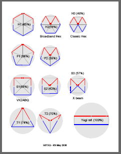
A systematic approach was taken to "optimise" the wire dimensions for 20m versions of the four antennas:
  • The reflector length was adjusted to place the peak F/B at 14.150 MHz.
  • The driver / reflector end spacing was adjusted to achieve a peak F/B ratio in excess of 30dB whilst trying to keep the worst case SWR around 2:1.
  • The driver length was adjusted to try to place the minimum SWR mid-band.
The final dimensions, using #16 gauge wire, which evolved from Free Space performance optimisation, were:
  • Hex beam: half-driver 219", half-reflector 207.8", end spacing 30", turning radius 130"
  • Pent beam: half-driver 219", half-reflector 208.7", end spacing 24", turning radius 135"
  • Square beam: half-driver 218", half-reflector 210.5", end spacing 22", turning radius 145"
  • Tri beam: half-driver 212", half-reflector 212", end spacing 40", turning radius 170"
The Free Space performance of the four antennas is compared below, alongside the performance of a full-size 2 element Yagi for reference:
Front to back ratio SWR Forward gainObservations
  • The Hexbeam, the Pentbeam and the Square beam are each capable of providing a peak F/B ratio in excess of 30dB, and a worst case F/B ratio of 12dB across the 20m band. The F/B performance bandwidth of these three antennas is very similar - the more "open" shape of the Hex and Pent reflectors compensating for the reduced size of these antennas compared to the square
  • The "closed" shape of the Tribeam reflector produces relatively narrowband F/B performance
  • The Hexbeam, the Pentbeam and the Square beam have similar SWR characteristics. With further minor optimisation it would be possible to achieve a worst case SWR below 2:1 for all three of these antennas
  • It proved impossible to place the Tribeam’s minimum SWR mid-band, or to get it below 2:1 at the lower band edge.
  • All four antennas exhibit the fall-off in gain with increasing frequency which seems to be typical of end-coupled wire beams. There is a spread of approximately 0.5dB in forward gain at the bottom of the band between the four antennas. At the top of the band, the spread between the Hexbeam, the Pentbeam and the Square reduces to 0.2dB; however the gain of the Tribeam has fallen much more dramatically.
Conclusions:
  • All four antennas provide useful beam performance in a space significantly smaller than a full-sized 2-element Yagi.
  • They lose out to the Yagi on forward gain, but have much superior Front/back ratios.
  • The Tribeam is probably the least attractive of the four antennas. Although it requires only 3 support spreaders, its performance bandwidth is significantly inferior to the others and it has an assymetric SWR curve - characteristics it shares with the Classic Hexbeam. It also has the largest turning radius at 170".
  • The three remaining shapes have very similar F/B and SWR performance to one another. The square shape provides marginally the best forward gain and requires only 4 support spreaders; however it is the largest of the four antennas. The Broadband Hexbeam is the smallest of the antennas considered, but it requires 6 support spreaders and has marginally the lowest forward gain. The Pentbeam size and performance sit neatly between those of the square and hexagon shapes.

Read more...