
ANTENNA EH 160 mt
Introduction
You'll not find in these pages the "bible" of EH, but just a simple description of my tests regarding this antenna;
I just want to share my test and result with other hams: nothing more.
EH inventor say that this antenna is based on a "new theory" which is very different from "Hertz theory": nothing to say about that, I can not say it' true or not;
You can read more directly on Ted's page (the inventor) (Ted Hart, w5qjr) or on Arno Elettronica (the italian promoter);
Here follow same words from the EH home page:
The Hart EH Antenna consists of two (2) elements having a natural capacity between them. (Think of a fat dipole) When a voltage is applied to a capacitor an E field will be developed. Also, the current through the capacitor (called displacement current) will develop an H field at right angles to (encircle) the electric field. However, when current flows through a capacitor, the phase of the current leads the phase of the applied voltage. Therefore, the phase of the H field leads the phase of the E field and the difference in phase (time) prevents satisfaction of the Poynting Theorem for this configuration.
If the external power applied to the EH antenna is first applied to an inductor between the source and the antenna, the inductor will retard the phase of the current relative to the applied voltage. Therefore, within the antenna the phase of the voltage (E Field) and the phase of the current (which causes the H Field) can be made to be the same. In other words, they occur simultaneously, thus, the name of the EH Antenna. This allows satisfaction of the Poynting Theorem and radiation occurs at the frequency where the reactance of the external inductance causes the phase of the current thru the capacitor to be the same as the applied voltage. This is at a frequency approximately equal to the resonant frequency of the external L and the internal C of the antenna. More complex phasing/matching networks and/or feedback techniques may be used to enhance bandwidth by maintaining the desired phase relationship over a range of frequencies. Greater amounts of radiation also result from more complex networks.
Due to the high efficiency of the integration of the E and H fields within the physical sphere of the antenna, where they are created simultaneously, the antenna need only be a very small fraction (less than 1%) of a wavelength. This is due to the very strong fields. The Poynting Theorem says Radiation = E x H. Since the space between the capacitor plates is only a fraction of a meter, the E field, measured in volts/meter, is large even for small applied voltages. The H field, measured in amp turns/meter, is large but relatively low, since the H field is less than the E field by a ratio of 377, the impedance of free space.
The EH Antenna can be physically configured to allow antenna pattern gain in the E plane in two different ways. One enhancement method is similar to that of a microwave horn, even though the operating frequency is such that the physical size of the antenna is very small compared to the operating wavelength. This is most evident in the Bi-cone version of the EH Antenna, where radiation occurs between and in a very small area at the apex of the cones, and the remaining cone area enhances the gain by shaping the antenna radiation pattern. The other method is to have long cylinders relative to the diameter of the antenna for the dipole configuration.
Due to the necessity of the H field being a closed loop (circle), the bi-cone must be non-directional in the H plane. In fact, all basic EH Antennas are non-directional in the plane orthagonal to the E field. Directive gain in the H plane may be achieved with phased arrays made of active EH Antennas, or special shapes.
Due to the E and H fields being primarily within the physical sphere of the antenna, Electro Magnetic Interference (EMI) is virtually eliminated. Since the E and H fields are contained, the EH Antenna can not be used as a parasitic element in an array.
Since the antenna is not a resonant structure, the frequency of operation is totally dependent on the external-phasing network. Since the typical phasing network only covers a small range of frequencies, the EH Antenna virtually eliminates harmonic radiation.
Since antennas are reciprocal, the EH Antenna offers full performance for both transmitting and receiving. In addition, since the E and H fields are primarily contained within the physical sphere of the antenna, the antenna rejects external E or H fields and receives only radiation. Thus, the EH Antenna is exceptionally quiet, thus producing very high signal to noise ratios in the presence of man made and atmospheric E field or H field noise.
Well, after this short introduction, i must say that I've built a EH antenna after I've heard:
"EH antenna, wich is just hundred time smaller then dipole, have the same gain and same performance of standard dipole".
That make me very curious so that I decided to build a 160 meter EH antenna, with the following measure (caming directly from Stefano, IK5IIR, the italian promoter).
Diameter of cylinders =25 cm
Height of cylinder= 37,5 cm
Distance between cylinder= 25 cm
Total Height (Cylinder + Network) 1,5 mt
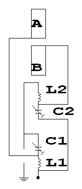
Needed Capacitance 128 Pf
Number of turns for L1=19
Number of turns for L2=16
So, if what people say about EH antenna is true, this very small antenna will perform as good as a full size dipole (80 mt in 160 mt band)...
The following pages are just a short technical describtion of EH I've built; at the end you'll find my test and results.
Now the first cylinder is ready;
Insert the first cylinder in the 250mm PVC pipe (10 cm) and lock with rivet; now make the second cylinder and cut the 250 mm PVC pipe at 45 cm: you will have a 37,5 cm cylinder + 25 cm space (PVC) and a second 37,5 cylinder
Lock the second cylinder with rivet;
Make 1 turn of wire on each cylinder as in picture;
Cut the wire longer (you will connect there the network,later); the upper "coil" wire will pass in the center while the bottom one on the side, near the cylinder.
At this point the antenna is ready, we need to made the network; in the first prototype I've used a 160mm PVC pipe (3 mt lenght) used also as support; on the upper side turn L2
then L1 using a 4mm wire; fix it with hot glue.
Let's make capacitor; in the first prototype I've used commercial variable capacitor as you can see in the picture.
Now we must add the two cylinder to the network obtaining a single "pipe"; in the first prototype I've used a threaded bar trought the two cylinder and the 160mm PVC pipe;
Make a hole for the SO239 connector.
The Eh is finished, let's tune it.
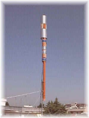
For a easy tune, I've mounted the antenna on a 3 mt PC pipe situated on my roof (the antenna is at 2 mt from the roof, 6 mt from the ground).
This prototype was wery hard to tune and instable;
When transmiting, S.W.R. changed quickly I suppose due to the small variable capacitor I've used;
With this antenna performance were very bad, but I went on with same modifications;
No comments:
Post a Comment