HIGH-FREQUENCY RADIO FUNDAMENTALS
For successful communication, HF radio performance depends on the type of emission (voice or burst device), transmitter power output, and type of antenna. The challenge facing HF radio operators is tremendous. They must use their HF radio systems to transmit important information to the DOB or AOB. The HF radio operator must continually adjust his system to compensate for changing conditions and missions. Knowledgeable operators, properly constructed antennas, and propagated frequencies are the key to successful, effective HF radio communication.
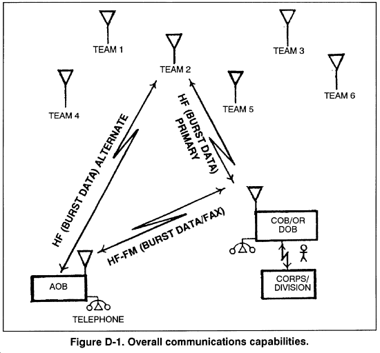
a. Of the variables that affect HF radio communication, the antenna is the one that an operator has the most control over. Proper antenna use greatly increases the chances of effective communication. Achieving the NVIS (near vertical incidence sky-wave) effect can be done with any antenna used with HF radios to help eliminate skip zones. This concept enables team RATELOs to establish communication with the COB or DOB. Consequently, NVIS enables the LRSU operations center to forward the information to the corps or division G2. (Figure D-1.)
b. Extensive training of team members on HF radio systems and antenna construction is essential to mission success. (See FMs 11-64, 11-65, 24-1, and 24-18 for more information.)
[edit]D-2. FREQUENCY PROPAGATION
High-frequency communication (2 to 30 MHz) is done by either ground-wave or sky-wave propagation. With low-powered, man-pack radios, ground-wave communication can be established out to 30 kilometers. High-powered vehicle-mounted equipment can extend that range to about 100 kilometers. The coverage from sky-wave communication can vary from several kilometers to thousands of kilometers.
a. Ground-Wave Propagation. Ground-wave propagation involves the transmission of a radio signal along or near the surface of the earth. The ground-wave signal is divided into three parts: the direct wave, the reflected wave, and thesurface wave (Figure D-2).
- (1) The direct wave travels from one antenna to the other in what is called the line-of-sight mode. Maximum line-of-sight distance depends on the height of an antenna above the ground; the higher the antenna, the further the maximum line-of-sight distance. Because the radio signal travels in the air, any obstruction (such as a mountain) between the antennas can block or reduce the signal. For an antenna 10 feet above the ground, 8 kilometers (5 miles) is the maximum line-of-sight distance.
- (2) The reflected wave reflects off the earth in going from the transmitting antenna to the receiving antenna. Together, the reflected wave and the direct wave are called the space wave.
- (3) The surface wave travels along the surface of the earth. It is the usual means of ground-wave communication. The surface wave depends on the type of surface between the two antennas. With a good conducting surface, such as seawater, long ground-wave distances are possible. If there is a poor surface between the antennas, such as sand or frozen ground, the expected distance for the surface wave is short. The surface-wave range can also be reduced by heavy vegetation or mountainous terrain.
b. Sky-Wave Propagation. Beyond the range covered by the ground-wave signal, HF communications are possible through sky-wave propagation. Skywave propagation is possible because of the bending (refraction) of the radio signal by a region of the atmosphere called the ionosphere.
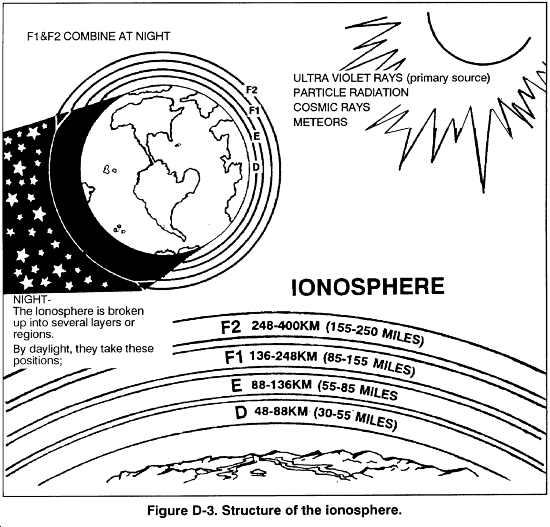
- (1) The ionosphere (Figure D-3) is an electrically charged (ionized) region of the atmosphere that extends from about 60 kilometers (37 miles) to 1,000 kilometers (620 miles) above the earth's surface. The ionization results from energy from the sun and causes radio signals to return to earth. Although the ionosphere exists up to 1,000 kilometers, the important area for HF communication is below 500 kilometers. This area is divided into four regions: D, E, Fl, and F2.
-
- (a) The majority of HF sky-wave communications depend on the F1 and F2 regions, with the F2 region being used the most for long-range daytime communications.
-
- (b) The E region is the next lower region. It is present 24 hours a day, although at night it is much weaker. The E region is the first region with enough charge to bend radio signals. At times, parts of the E region become highly charged and can either help or block out HF communication. These highly charged areas are called sporadic E. They occur most often during the summer.
-
- (c) The D region is closest to earth and only exists during the day. It cannot bend a radio signal back to earth, but it does play an important role in HF communication. The D region absorbs energy from the radio signal passing through it, thereby reducing the strength of the signals.
- (2) The bending of the radio signal by the ionosphere depends on the frequency of the radio signal, the degree of ionization in the ionosphere, and the angle at which the radio signal strikes the ionosphere. At a vertical (straight up) angle, the highest frequency bent back to earth is called the critical frequency. Each region of the ionosphere (E, Fl, and F2) has a separate critical frequency. For a vertical angle, signals above the highest critical frequency pass through all ionospheric regions and on into outer space. Frequencies below the critical frequency of a region are bent back to the earth by that region; however, if the frequency is too low, the signal is absorbed by the D region. To have HF sky-wave communication, a radio signal must be a high enough frequency to pass through the D region, but not so high a frequency that it passes through the reflecting region. Thus, radio operators must have current propagation charts from which to choose the most effective frequency during a given time period. To achieve an NVIS effect, the radio operator subtracts 20 percent from frequencies propagated on commercial computer propagation programs.
- (3) The angle at which a radio signal strikes the ionosphere plays an important part in sky-wave communication. As mentioned, any frequency above the critical frequency passes through the reflecting region. If the radio signal having a frequency above the critical frequency is sent at an angle, the signal is bent back to earth instead of passing through the region. This can be compared to skipping stones across a pond. If a stone is thrown straight down at the water, it penetrates the surface. If a stone is thrown at an angle to the pond, the stone skips across the pond. For every circuit, there is an optimum angle above the horizon called the takeoff angle. It produces the strongest signal at the receiving station. This optimum takeoff angle is used to select the antenna for a specific circuit. By placing an antenna between 1/8 wavelength and 1/4 wavelength above ground level, the radio operator achieves an NVIS effect and reduces or eliminates any skip zone.
- (4) Depending on the frequency, antenna, and other factors, an area may exist between the longest ground-wave range and the shortest sky-wave range where no signal exists. This is called the skip zone and no communication is possible (Figure D-4). The NVIS effect can eliminate this problem.
- (5) HF propagation involves much more than what has been presented. For example, multiple frequencies are usually needed to maintain sky-wave communication. As a minimum, two frequencies, one for day and one for night are normally required.
[edit]D-3. ANTENNA THEORY AND CONSTRUCTION
To select antennas for HF radio communication, the operator needs to know the concepts. This paragraph defines several basic terms and relationships, helping the operator select the best antenna.
a. Wavelength and Frequency. In radio communication, there is a definite relationship between antenna length and frequency wavelength. This relationship is important when building antennas for a specific frequency or frequency range. The wavelength of a frequency is the distance an electromagnetic wave travels to complete one cycle. (See Figure D-5.)
b. Resonance. Antennas are classified as either resonant or non-resonant, depending on their design. Both resonant and non-resonant antennas are commonly used on tactical circuits.
- (1) A resonant antenna matches the length of a frequency's wavelength. In a resonant antenna, almost all of the radio signals sent to the antenna are radiated. If a resonant antenna is used for radio communication, a separate antenna must be built for each frequency used with the radio.
- (2) If the antenna is used for a frequency other than the one it matches, it is nonresonant and much of the signal is lost. A nonresonant, or broadband, antenna effectively radiates a broad range of frequencies with lower efficiency. When a nonresonant antenna is used, large losses of signal power occur. Signal energy from the antenna is reflected and causes standing waves on the antenna. A measure of these standing waves, called standing wave ratio, is used to determine if an antenna is resonant at a particular frequency. A 1-to-1 standing wave ratio is the ideal situation, but 1.1-to-1 is about the best that can be done. When building wire antennas, the length of the antenna should be adjusted until the lowest standing wave ratio is measured. A 3-to-1 standing wave ratio is acceptable (check the operator's manual for the particular radio in use to determine the maximum standing wave ratio that the radio can tolerate.) In some radios, the power output of the transmitter is automatically lowered if the standing wave ratio is too high.
c. Polarization. Polarization is the relationship of radio energy radiated by an antenna to the earth. The most common polarizations are horizontal (parallel to the earth's surface) and vertical (perpendicular to the earth's surface); however, others, such as circular and elliptical, also exist. A vertical antenna normally radiates a vertically polarized signal, and a horizontal antenna normally radiates a horizontal signal. In HF ground-wave, both the transmit and receive antennas should have the same polarization for best communication. In the case of HF ground-wave propagation, vertical polarization should be used. For HF sky-wave propagation, the polarization of the transmitter and receiving antennas does not have to be the same because of the random changing of the signal as it is bent by the ionosphere. This random changing allows the use of vertical or horizontal polarization at the transmitter or receiving antenna. For sky-wave propagation, horizontal polarization is recommended to be most effective.
d. Classification. Antennas are classified according to how radio energy is radiated: omnidirectional, bidirectional, or directional.
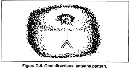
- (1) 0mnidirectional. An omnidirectional antenna radiates radio energy in a circular pattern so all directions on the ground receive an equal amount of radiation (Figure D-6). The most common omnidirectional antenna is the whip. Other examples are the quarter-wave vertical (RC-292, OE-254) and the crossed dipole (AS-2259). The omnidirectional antenna radiates and receives energy equally well in all compass directions. This antenna is used when it is necessary to communicate in separate directions at once. However, it is also more susceptible to interference from all directions.
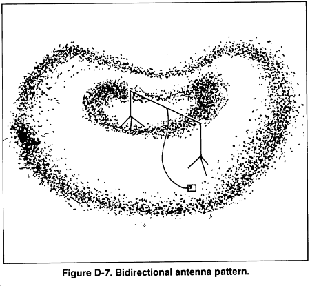
(2) Bidirectional. A bidirectional antenna has two main lobes of radio energy opposite each other with a null between the lobes (Figure D-7). These antennas produce a stronger signal in the two opposing directions while reducing the signal in other directions. The tactical bidirectional antennas most commonly used are sloping wires, random length wires, and half-wave dipoles. Bidirectional antennas are usually used on point-to-point circuits and in situations where the antenna null can be positioned to reduce or block out interfering signals when receiving. Although bidirectional antennas are more difficult to find direction (ground-wave), they can be used when several antennas are closely located. Placement of other antennas in the null of bidirectional antennas reduces interference and interaction between the antennas. A drawback of bidirectional antennas is that they have to be correctly oriented to radiate in the desired directions. However, lowering the antenna to create the NVIS effect increases the radiation pattern allowing less accuracy in orientation of the antenna.
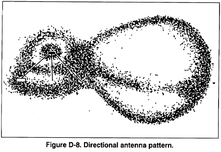
(3) Directional. A directional antenna has a single large lobe of radio energy in one direction (Figure D-8). It is much like a bidirectional antenna with one of its lobes cut off. Several bidirectional antennas (long-wire, sloping-Vee) are made directional by adding a terminating resistor that absorbs the second main lobe. A terminating resistor matches the antenna. A terminating resistor must be able to absorb one-half the power output of the connected transmitter and provide 400 to 600 ohms of resistance. A directional antenna concentrates almost all the radio signal in one specific direction; therefore, it must be carefully oriented. Depending on the antenna design, the main lobe of a directional antenna can cover 60 degrees or more or be a narrow pencil beam. Directional antennas are used on long-range point-to-point circuits where the concentrated radio energy is needed for circuit reliability. Directional antennas are difficult for the enemy to find the direction of transmission.
e. Antenna Construction and Selection. Antenna construction is limited only by imagination. There are many types and configurations. However, the operator must be careful not to construct an antenna that has a high standing wave ratio, which can damage radio equipment. Standing wave ratio meters should be used when testing or using unfamiliar antennas. In selecting an antenna for an HF circuit, the operator must know the type of propagation.
- (1) Ground-wave propagation requires low takeoff angles and vertically polarized antennas. The whip antenna provides good omnidirectional ground-wave radiation. If a directional antenna is needed, the operator selects one with a good low-angle vertical radiation.
- (2) Sky-wave propagation makes the selection of an antenna more complex. The first step is to find the distance between radio stations so that the required takeoff angle can be determined. The takeoff angle versus the distance tables gives approximate takeoff angles for day and night sky-wave propagation. If the circuit distance is 966 kilometers (600 miles) during the day, the required takeoff angle is about 25 degrees. At night, it is 40 degrees. Therefore, the operator selects an antenna that has high gain from 25 to 40 degrees. This step can be omitted if the propagation predictions give the required takeoff angles. By subtracting 20 percent from these predictions for use with NVIS constructed antennas, the operator uses a planning range of 0 to 300 miles for short-range HF communication.
- (3) The radio operator decides what type of coverage is required. If the radio circuit consists of mobile (vehicular) stations or many stations at different directions from the transmitter, an omnidirectional antenna is required. If the circuit is point to point, a bidirectional or a directional antenna can be used. Normally, the receiving station locations dictate this choice.
- (4) Before an antenna can be selected, the operator examines the materials available for antenna construction. If a horizontal dipole is to be erected, at least two supports are needed. (A third support in the middle is required for frequencies of 5 MHz or less.) If these supports are not available and there are no other items that can be used as supports, the dipole cannot be used. The operator checks the site of the antenna to determine if the proposed antenna will fit.
- (5) Another consideration is the site itself. More times than not, the tactical situation determines the position of the communication antennas. The ideal setting is a clear flat area with no trees, buildings, fences, power lines, or mountains. Unfortunately, such an ideal location is seldom available for the tactical communicator. In choosing an antenna site, the radio operator selects an area as flat and as clear as possible. In many situations, an antenna must be put up in less ideal sites. This does not mean that the antenna will not work, but that the site affects the pattern and functioning of the antenna.
f. Half-Wave Dipole Antenna. The half-wave dipole is a balanced resonant antenna (Figure D-9). It produces its maximum gain for a narrow range of frequencies, normally 2 percent above and below the design frequency. Since frequency assignments are normally several megahertz apart, the operator must build a separate dipole for each assigned frequency. The length of a half-wave dipole is calculated from using the following formula:

The height of a dipole is normally kept at 1/4 wavelength to 1/2 wavelength above ground level for long-range sky-wave. For NVIS (O to 300 miles), the antenna should be erected between 1/8 wavelength and 1/4 wavelength above ground level. This rule also applies to the inverted Vee and sloping Vee antennas.
g. Inverted Vee. The inverted Vee, or drooping dipole, is similar to a dipole but uses only a single center support. Like a dipole, it is used for a specific frequency and has a bandwidth of plus or minus 2 percent of design frequency. Because of the inclined sides, the inverted Vee antenna produces a combination of horizontal and vertical radiation; vertical off the ends and horizontal broadside to the antenna. All the construction factors for a dipole also apply for the inverted Vee. The inverted Vee has less gain than a dipole, but the use of only a single support could make this the preferred antenna in some tactical situations. (See Figure D-10).
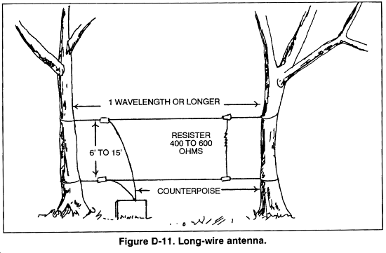
h. Long-Wire Antenna. A long-wire antenna is one that is long compared to a wavelength. A minimum length is 1/2 wavelength; however, antennas that are at least several wavelengths long are needed to obtain good gain and directional characteristics. The construction of long-wire antennas is simple and straight forward. The dimensions or adjustments are critical. Along-tire antenna accepts power and radiates it well on any frequency for which its overall length is not less than 1/2 wavelength (Figure D-11).
- (1) Along-wire antenna is made directional by placing a terminating resistor at the distant station end of the antenna. The terminating resistor should be a 600-ohm noninductive resistor capable of absorbing at least one-half of the transmitter power. Terminating resistors are part of some radio sets. They can also be locally made, using supply system parts (National Stock Number 5905-00-764-5573, 100-watt, 106-ohm resistor).
- (2) Building a long-wire antenna only requires wire, support poles, insulators, and a terminating resistor (if directionality is desired). The only requirement is that the antenna be strung in as straight a line as the situation permits. The height of the antenna is only 15 to 20 feet above ground so that tall support structures are not required.
i. Sloping Vee. The sloping Vee is a short- to long-range sky-wave antenna that is reasonably simple to build in the field (Figure D-12). The gain and directivity of the antenna depend on the leg length. For reasonable performance, the antenna should be at least 1/2 wavelength long. To make the antenna directional, terminating resistors are used on each leg on the open part of the Vee. The terminating resistors should be 300 ohms and be capable of absorbing one-half of the transmitter's power output. These terminating resistors are either procured or are locally made. Using the terminating resistors, the operator aims the antenna so that the line cutting the Vee in half is pointed at the distant station.
[edit]D-4. FIELD-EXPEDIENT TECHNIQUES
Operators must know the importance of field-expedient antennas. Field-expedient antennas are necessary if conventional antennas are damaged or missing parts.
a. Repair of Damaged Antenna. A broken whip can be temporarily repaired in several ways.
- (1) If the whip is broken in two sections, the operator can join the sections. First, the radio operator removes the paint and cleans the sections where they join to ensure a good electrical connection. He places the sections together and secures them with bare wire or tape. (See Figure D-13.)
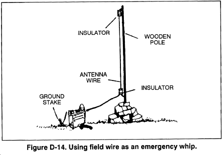
- (2) If the whip is badly damaged, a length of field wire (WD1/TT) of the same length as the original antenna can be used. The radio operator removes the insulation from the lower end of the field wire antenna, twists the conductors together, sticks them in the antenna base connector, and secures it with a wooden block. The antenna wire is supported by a tree or a pole (Figure D-14).
b. Insulators. Insulators can be made from items that are readily available. The operator should be careful when selecting any material that holds water (cloth, rope). In a rainstorm, these items absorb water and lose their insulating characteristics. (See Figure D-15.)
c. Supports. Many expedient antennas require supports to hold the antenna above the ground. The most common supports are strong trees that can survive heavy windstorms. However, even the largest trees sway enough in the wind to break wire antennas. To keep the antenna taut and to prevent it from breaking or stretching as the trees sway, the operator attaches a spring or piece of old inner tube to one end of the antenna. If a small pulley is available, he attaches the pulley to the tree and passes a rope through the pulley. Then, he attaches the rope to the end of the antenna, and attaches a heavy weight to the other end of the rope. This allows the tree to sway without straining the antenna.
d. Terminating Resistors. Terminating resistors have been a continual problem for the field communicator. Resistors for low-power (man-pack) HF radios are readily available from commercial radio supply stores. Carbon resistors that can dissipate more than 5 watts are hard to find. However, the 5-watt resistors can be connected in parallel to make a terminator to handle greater power. For example, eight 5-watt, 4,000-ohm resistors connected in parallel results in a 500-ohm, 40-watt terminator. The 5-watt resistor still does not solve the problem of high power HF terminators. A terminator for a 1,000-watt transmitter requires 100 5-watt resistors. A 100-watt, 106-ohm resistor (National Stock Number 5905-00-764-5573) can be mounted in series on a single insulating board to form a terminator for high-powered transmitters.
e. Expedient Wire. If regular antenna wire is not available, the radio operator can use field telephone wire (WD1/TT.) to build antennas. Field wire consists of two insulated wires. Each insulated wire is made up of four copper strands and three steel strands of wire.
- (1) When making electrical connections with field wire, the operator uses the copper strands. To identify the four copper strands, he removes about 1 inch of insulation from one end of the insulated wire. He holds the wire where the insulation ends and the strands are bent to the side. When he releases bending pressure, the steel strands snap back to their original position while the copper strands remain bent. These copper strands can then be wrapped around the steel strands to present a copper surface for a good electrical connection.
- (2) If field wire is used as the radiating element of an antenna, the two insulated wires in the twisted pair must be connected together at the ends so that electrically the two wires act as one. First, the radio operator tightly twists together all six steel strands from the two wires (for strength). He twists the eight copper strands together (for electrical connection). Then, he twists the copper strands around the steel strands.
- (3) When used as a feed line for a dipole antenna, the radio operator connects each of the two insulated wires of the twisted pair to a separate leg of the dipole. At the radio, he connects one wire (any wire) to the center connector of the radio antenna terminal and the second wire to a screw on the antenna case.
- (4) In an emergency, any wire of sufficient length can be used for an antenna; for example, barbed wire, electrical wire, fence wire, and metal-cored clothesline. Communication has been successful using metal house gutters and even metal bed springs. A radio operator's mission is not completed until communication is established.
f. Grounding. A good electrical ground is needed for two reasons: first, to protect the operator and his equipment; and second, as a radio frequency ground needed by some antennas to function properly. Most radio sets come with a ground rod that should provide enough ground if used properly in good soil. The radio operator ensures the ground rod is free from oil or corrosion. He ensures the rod is driven into the ground so that the top of the rod is below surface. To ensure a good electrical connection, the top of the ground rod and the end of the ground strap should be clean and bright. A clamp or nut and bolt should be used to make a good mechanical and electrical connection at the ground rod. The end of the ground strap and the radio ground connection should both be cleaned before connection is made.
NEVER USE ANY PIPING OR UNDERGROUND TANKS THAT CONTAIN
FLAMMABLE MATERIALS (SUCH AS NATURAL GAS OR GASOLINE).- (1) If a ground rod is not available, water pipes, concrete reinforcing rods, metal fence posts (protective paint coating removed), or any length of metal can be used. If a water system uses metal pipe, a good ground can be established by clamping the ground strap to a water pipe. Underground pipes, tanks, and metal building foundations also work.
- (2) In dry soil, electrical grounds can be improved by adding water and chemicals to the soil. Two common chemicals are epsom salt and common table salt. Epsom salt is preferred because it is not as corrosive as table salt. The radio operator makes a solution of one pound of chemical to one gallon of water. He slowly pours the solution in a hole dug around the ground rod. Water should be added periodically to keep the area damp. If water is not available, urine can be used.
- (3) Multiple ground rods can also be used to improve electrical grounds. If enough rods are available, a "star ground" can be built. A single rod is driven in the center of about a 20-foot circle. Ground rods are driven along the outside of the circle. The ground strap from the radio is connected to the center rod, which in turn is connected to the rods along the outside of the circle. The rods on the outside of the circle should also be connected together.
- (4) All radio equipment should be grounded to prevent shock and damage to equipment during electrical storms.
[edit]D-5. LONG-RANGE SURVEILLANCE COMMUNICATIONS EQUIPMENT
The LRS community uses many different types of communications equipment. This paragraph describes the type and quantity of authorized equipment for LRS companies and detachments. The goal is to standardize equipment in all LRS units.
a. Team HF Radio, AN/PRC-104. The AN/PRC-104 is a lightweight radio transceiver that operates in any frequency between 2.0000 and 29.9999 Mhz. Power output is 20 watts. It operates in upper sideband (LRS mission) or lower side band. It is easy to install and operate, and it is well suited for LRS missions. Each team is authorized one radio. (See TM 11-5820-919-12 for more information.)
b. Team VHF (FM) Radio, AN/PRC-126. The AN/PRC-126 is a hand-held two-way radio used primarily for interteam communication and ground-to-air communication (extraction). Each team is authorized two radios. (See TM 11-5820-1025-10 for more information.)
c. Digital Message Device Group, OA-8990/P. The OA-8990/P is used for message bursts between teams, COB or DOB, and AOB. It stores up to 8 messages in receive memory. A free text or 5-character group format may be used. It is National Defense Area-secure, and messages that are transmitted using this device are encrypted by the operator. Each team is authorized one digital message device group (four per AN/TSC-128) or one KL43CS per team (four per AN/TSC-128). (See TM 11-5820-887-10 for more information.)
d. Base Radio, AN/GRC-213. The AN/GRC-213 is a vehicular-mounted, low-power (20 watts) HF radio used for communication between deployed teams and the COB or DOB and AOB. It has the same transceiver as the PRC-104. Each AN/TSC-128 is authorized three radios. (See TM 11-5820-923-12 for more information. )
e. Base Radio, AN/GRC-193. The AN/GRC-193 is a vehicular-mounted, medium- and high-power HF radio with a power output of either 100 or 400 watts. It is used for communication between teams and the COB or DOB and AOB. Each AN/TSC-128 is authorized one radio. (See TM 11-5820-924-13 for more information.)
f. Encryption Message Burst Device, KL-43C. The KL-43C is an off-line encryption terminal to send and receive classified messages over unprotected telephone lines and radio nets. It stores up to two messages in memory. It is small and lightweight, and replaces the OA-8890 digital message device group on a one-for-one basis. Each team is authorized one device (four per AN/TSC-128).
g. Antenna, AN/GRA-50. The AN/GRA-50 is a component of the AN/PRC-104, AN/GRC-213, and AN/GRC-193 radios. It is a half-wave dipole that can be used for either long-range (2500 miles) or short-range sky-wave (NVIS, 0-300 miles). (See TM 11-5820-467-15 for more information.)
h. Antenna, AS-2259/GR. The AS-2259/GR is a component of the AN/PRC-104, AN/GRC-213, and AN/GRC-193 radios. It consists of two inverted Vee dipoles positioned at right angles. It uses a foam-electric center pole as its coaxial. It uses the NVIS concept to achieve a range of 0 to 300 miles. (See TM 11-5985-379-14& P for more information.)
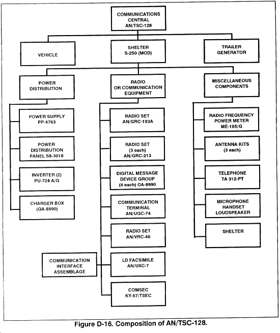
i. Communication Shelter, TSC-128. Six TSC-128s are authorized per corps LRS and four per division LRS. The AN/TSC-128 is the principal component of the long-range surveillance base radio station. One base radio station is made up of two AN/TSC-128s. The LRSC has three base radio stations (six AN/TSC-128s). The LRSD has two base radio stations (four AN/TSC-128s). See Figure D-16, for the composition of the AN/TSC-128.
- (1) The AN/TSC-128 provides both reception and transmission capability for land-secure-burst data communication over extended ranges, using two identically configured AN/TSC-128 shelters with five or less antennas (three is the preferred number).
- (2) The AN/TSC-128 provides continuity during operations to include maintenance periods. Continuity is required during corps and division displacement. Continuity is achieved by using two shelters.
- (3) The AN/TSC-128 receives and records at least 2 messages simultaneously, and it can process a minimum of 18 messages in one hour. It allows selective retransmission of messages to the corps or division tactical operations center over the local or wide area communication system.
- (4) The AN/TSC-128 provides informal record traffic to be originated and terminated by the LRSU base radio station and communicated to the TOC support element and the MI battalion headquarters.
[edit]D-6. SITE SELECTION
The reliability of radio communication depends largely on the selection of a good radio site. The site should satisfy technical, tactical, and security requirements. Several important factors must be considered when setting up a radio site. The site must be accessible from the hide site. It must be defendable since escape from the enemy will not be as fast as with a full LRS team. An important consideration is the use of terrain to aid in communication. Also, the site must have good cover and concealment without interfering with the erection of antennas. Moving the site may be necessary if interference (man-made or not) becomes a problem.
a. An alternate site should also be planned. Also, the radio operator considers the following:
- Always use a resonant antenna if possible to communicate.
- Always try to use a directional antenna.
- Remember that WD-1 is insulated, but not shielded. Using it as a lead-in wire to the antenna causes it to lose signal strength before it reaches the antenna.
b. The COB or DOB is the primary link between the deployed teams and corps or division G2. COB or DOB stations are normally located well within the security umbrella of the corps or division main and should be close enough to the G2 section to facilitate a wire line for reporting purposes. The AOB may collocate if communication is established and maintained between the deployed teams and the COB or DOB. For increased survivability and redundancy, the AOB may be located elsewhere such as the corps or division rear. If communication cannot be established or maintained between the teams and the COB or DOB, the AOB is moved forward or rearward (mission dictated) to establish communication with the deployed teams and the COB or DOB. When the AOB is used as the primary reporting link, it must maintain a constant communication path with the COB or DOB, while the COB or DOB moves with the corps or division main









No comments:
Post a Comment