Tuesday, February 28, 2012

A Practical, 5-Band Homebrew Wire Beam -- the Upside-Down Umbrella

A Practical, 5-Band Homebrew Wire Beam -- the Upside-Down Umbrella


Experimenting with antennas -- God love ‘em -- is still one area of amateur radio where we can all test, concoct, homebrew, and then see the results of our labors almost instantly. For many of us, it is a real thrill to string some wire from some trees or bolt together some aluminum and noticeably improve our ability to snag signals out of the sky or fling RF into the ether.

Let’s all agree that there is little that is new in the area of antennas. And what there might be is probably beyond the reach -- technically, economically, and engineering-wise -- of most of us. But we can always borrow, filch, modify, and just plain steal from work that has gone on before us and adapt and develop antennas that meet our specific needs. Antennas that give us that thrill when they work better than whatever we were using before. Or teach us something if they are not.

So, I wanted an HF beam. My vertical, my G5RV, my skywire horizontal loop, and my multi-band dipole all do a reasonably good job from 160 through 6 meters. They enabled me to work more than 200 countries with only 100 watts since I returned to being active in 2005. But I yearned for more. And I craved a new project.

I actually purchased a used Cushcraft MA-5B mini-beam and planned to put it atop a 50-foot Rohn 20G tower I acquired. The MA-5 covers 10 through 20 with two elements on 10, 15 and 20 and is a rotatable dipole on 12 and 17. But the lure of building something on my own kept tugging at me. The MA-5 is still wrapped in the package the OM from whom I bought it shipped it to me. Instead, I decided to go out and build myself a “beam.”

Research:

I had a few specifics in mind when I started researching the various possibilities for building an HF beam antenna.
Some signal gain in a specific direction
Side and front-to-back signal rejection
Small wind load -- less than 10 pounds (the 20G is light duty tower)
As small a rotation radius as possible (trees, trees, trees!)
Multi-band capability, hopefully for 10 through 20 meters including WARC bands
Reasonable cost by using readily available materials
And the biggie, something I could build myself, since I don’t have access to a machine shop and I do have five thumbs on each hand 

The Internet provides all the information one could want for researching various possibilities, plus there are many good antenna books that have suggestions as well. I looked at Moxons, quads, spider beams, vertical arrays, and more. Each had its good points and several of them seemed to be within my capabilities to build. Then, as I learned more, my interest returned to a particular antenna I had considered when I first returned to the air three years ago.

The commercial version of that antenna is called a “hex-beam” and it is manufactured by Mike Traffie N1HXA. (http://www.hexbeam.com/) The antenna gets very good reviews on the various ham radio web sites, as does the company’s customer service. They are manufactured in monoband and 5-band versions. Some of Traffie’s models are specifically designed for portable operation and are great solutions for those who like to operate from distant mountaintops and want a good directional antenna to carry along and quickly set up. The specs on Mike’s web site are quite interesting and seem to be honestly depicted. I see no reason to doubt their accuracy. The venerable Lew McCoy W1ICP (SK) wrote a glowing report on the antenna in CQ Magazine.


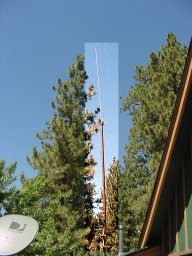
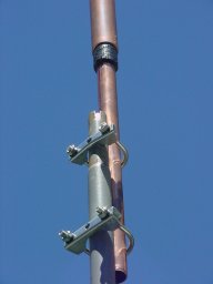
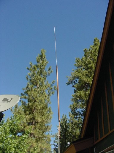
N4KC’s upside-down umbrella antenna, mounted at about 47 feet.

Well, the “hex” seemed to meet all my criteria. Now, I had to decide if it was something I could build myself or if I should start hinting to the proper people about what a great Christmas present Traffie’s creation would make.

As designed by N1HXA, the 5-band hexbeam consists of three pieces of wire for each band. Two of the wires are deployed as a center-fed radiating element and the other acts as a director, making it a two-element beam for each band on which it is designed to operate. The elements are strung around six Fiberglass spreaders that act as supports. The longest wires, the 20-meter elements, carry the tension and pull the spreaders up into a configuration that looks for all the world like an upside-down umbrella without the fabric covering. The shorter wires that make up the elements for the other bands are strung around the upturned spreaders, spaced a distance apart so there is little or no interaction between them. The 10-meter ones are at the bottom, about six inches above the baseplate that holds the bottom ends of the spreaders. In order to keep the turning radius as small as possible, the elements are horizontally arrayed in the shape of the letter W up and down the spreaders (See the graphic below that shows a top-looking-down view of the shape of the wire elements. The spreaders are not shown).


Note that the driven element is fed in the middle and offers about a 50-ohm load. The center of the W for each band’s driven element attaches to two points on a center post, arrayed from the 10-meter wires nearest the baseplate to the point near the top of the post that lines up with the 20-meter element. The antenna itself is fed from the top and Traffie’s version runs a feedline down the middle of the center post, connecting each band’s feed point together. Yes, the beam uses a single feedline for all five bands. Traffie’s reflector is also shaped in the form of a W, presenting a mirror image of the driven element. The point where the ends of the driven element and reflector approach each other is critical in its spacing and employs a spreader to help establish the correct distance and keep it constant.

As I researched farther, though, I learned that several hams had been experimenting with their own homebrew versions of the beam. Steve Hunt G3TXQ had been modeling and building versions of it for some time and had been generous enough with his work to publish it on the Internet (http://karinya.net/g3txq/hexbeam/) as well as in some amateur radio publications. He had also done considerable work in an effort to get even better front-to-back ratio and increase the already broad bandwidth of the Traffie’s hex-beam. Steve had found that by making the reflector a broad U shape around the outside of the spreaders instead of the mirror-image W shape, and by changing the dimensions of the elements, he could make considerable improvement. From his models, the antenna achieved a less than 2:1 SWR throughout all the design bands. 10 meters did not quite manage less than 2:1 across the entire band but it was within reach of the internal tuner in most rigs. The only compromise was that the turning radius increased from about 9 feet to a little less than 11 feet and added a pound or so to the weight.

Back in the USA, Leo Shoemaker K4KIO was taking Steve’s modeling results and developing techniques for turning them into a real in-the-air antenna. In addition, like Steve, he was willing to share his detailed construction recommendations on his well-done web site.
 (http://www.leoshoemaker.com/hexbeambyk4kio/general.html) The more I studied Leo’s site and read the results of his experimenting, the more excited I became about trying to string this baby together and see how it played. I already had some of the parts I would require including wire and rope. I needed some of the rest -- paint, liquid electrical tape, liquid nails, wire lugs, tie wraps—for other projects anyway -- including some which are decidedly non-ham-radio in case the wife reads this.

By the way, there is a very active hex-beam Yahoo group (http://groups.yahoo.com/group/hex-beam/?v=1&t=search&ch=web&pub=groups&sec=group&slk=1) that talks about the commercial version as well as the homebrew types. The members were encouraging and helpful. And the way Leo described things, building one of these things actually seemed doable.

Doable and worth the trouble! This is not a four-element, wide-spaced mono-band beam. It will not work miracles. It won’t blow holes in pileups. Anyone who thinks it will perform as well as a SteppIR or a full-size Yagi is due to be disappointed. That being said, the thing does appear to do a very good job, considering its size, weight and cost. Many claim it will do far better than it ought to, but I don’t know.

It also seems forgiving of being deployed at low heights and even performs best for most applications at around 50 feet above the ground. Its wind load -- as built following K4KIO’s suggestions -- is less than 6 pounds. Since it is a uniform size and weight and circular in shape, it is not nearly as wind resistant as a conventional beam. As typically constructed, the broadband version of the six-spreader wire beam weighs in at around 20 pounds. That makes it possible to launch it on a push-up mast and rotate it with a light-duty rotator.

On his web site, G3TXQ does an interesting comparison between his broadband antenna (as modeled), the Cushcraft MA-5B two-element beam (like the one still in the shipping package out in my basement), and the HyGain TH11DX, which is, by all accounts, a fine HF antenna. He shows the comparison measurements for 20 meters and also takes a look at their turning radii, weight, and wind load (commercial beam specs based on material published by the manufacturers).

Well, much as I would love to have the gain and front-to-back ratio of the HyGain, I simply do not have the area to rotate it (remember my trees, trees, trees?). I am also not quite ready to invest in a tower that would safely hold it. Though there are no antenna restrictions in my town, I still want to remain relatively transparent to neighbors. Being stealthy is another plus of the upside-down umbrella (see below). By the way, some builders maintain the gain of the hexagonal wire beam is somewhere north of 5 dBd on some bands. But even at G3TXQ’s modeled gain predictions, the upside-down umbrella has considerably more gain than the 2-element Cushcraft (especially on 17 and 12 where the MA5B has NO gain…it IS a dipole). It certainly appeared to me that the antenna was worth building.

Preparing for Construction:

Okay, I admit it right here in front of everybody. I am not that handy. Not only have I always been a klutz, but an auto-immune neurological disorder I contracted a few years ago left me with limited fine motor skills. I have trouble holding things like nuts and bolts. Still, looking at Leo’s suggested construction notes, ( http://www.leoshoemaker.com/hexbeambyk4kio/broadhexbuildingnew.html) I decided I could do it. I started gathering the additional stuff I needed.

Two areas had me just a little skittish. One was the spreaders. Some have used PVC pipe, which is cheap and readily available, but they found it tended not to be able to maintain the umbrella shape of the beam. PVC also needs lots of paint to protect it from UV rays. Others have tried cane poles but they, too, have trouble holding up under the strain of maintaining the distinctive shape that keeps the wire elements optimally spaced. On his site -- and for no compensation -- Leo mentions Max-Gain Systems in Atlanta. (http://www.mgs4u.com/index.html) I will also mention them -- for no compensation -- because they offer a fiberglass spreader kit, already specifically cut to the dimensions recommended by K4KIO. That also saves money on shipping. You may be able to find another source for lower price, but this seemed like a reasonable deal to me. I see the Max-Gain guys at hamfests and know they offer good quality merchandise, so I decided to buy the fiberglass spreaders for this project from them. They arrived as promised two days after ordering, all nicely cut and fitting together perfectly. I also have a bunch of 4-foot fiberglass sections left over for other projects, too.

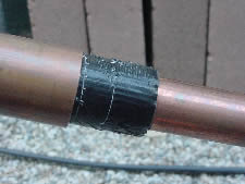
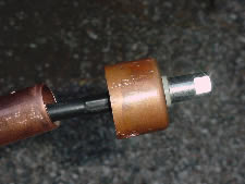
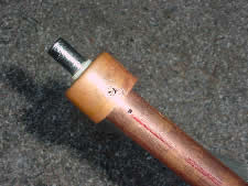
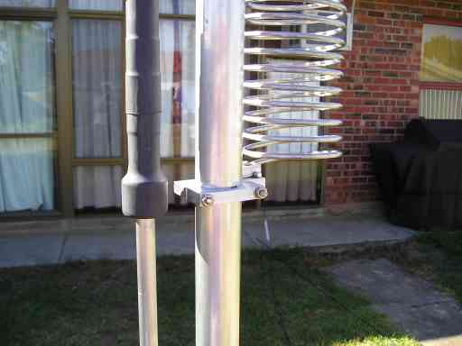
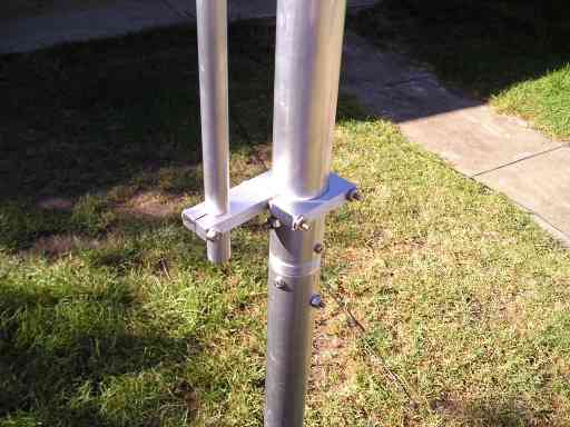
The second concern was the baseplate, the device onto which the spreaders are mounted. This is the true “heart” of the antenna, where the spreaders spread out from, and where the center post passes through. Some hams use plastic-type or tough polyurethane plates or even plywood. These can work, depending on the amount of stress the spreaders and mast put on it or how much weight it adds to the antenna. However, I did not feel that “cutting board” type plastic would be sturdy enough and plywood would eventually succumb to the weather, no matter how much paint I used. I located a supplier who sold aluminum, cut to any shape I wanted, but I had no idea how I would drill out the holes. I only have a cordless hand drill, and I suppose I could have accomplished the task with lots of patience, bit replacement, and battery recharging, but I was worried about getting the holes in the right place. I really wanted this crucial part of the antenna to be precise and tight.

Enter Ron Mott W4RDM. (http://hexkit.ronmott.net/) I saw on the Yahoo hexbeam reflector that he was offering a pre-drilled aluminum baseplate and all the U-bolts and hardware a guy needed for K4KIO’s version. That included a pair of floor flanges that Leo discovered that nicely reinforce the point where the center post runs through the baseplate. (Some people only use one of the flanges but again, that seems like a pretty crucial point for the antenna and two is better.) At first blush, I thought the cost for Ron’s plate and accessories was a little high. Then I priced aluminum plates -- before doing all that measuring and marking and drilling -- and the big-box-hardware-store prices on U-bolts, floor flanges, and the bolts, washers, and nuts to do the job right. I quickly got on Ron’s web site and ordered a plate before he realized he was selling them too cheap. He was kind enough to deliver the whole package to me at the Huntsville, Alabama, Hamfest to save shipping.

(Max-Gain now offers a parts kit (http://www.mgs4u.com/hexbeam-kit.htm) for this antenna that includes pre-cut fiberglass spreaders, wire, and rope. WI4USA (http://www.wi4usa.com/) is selling a full kit and instructions for building the G3TXQ version, too. I have not tried either kit so I can’t give recommendations, but they certainly seem worth checking out if you don’t want to gather up all the necessary parts yourself.)

Building the Beast

Once I had everything gathered up, actual construction went very quickly. The wire elements are attached to the center post and the feedline using bolts and nuts that are stuck through holes I measured and drilled in the Fiberglass. Getting those nuts poked through the holes, using K4KIO’s coat-hanger idea for sticking them through from inside the pipe, proved to be a bit tough for me. I did better when I got a stronger coat hanger to use and got it done, though.

The antenna also uses a single coax feedline and short coax jumpers are employed to connect the center-post bolts where each set of driven-element wires are hooked up to be fed. I made my jumpers from RG-8U since I planned on running some power at some point. Getting them cut to the exact length and bolted in place was quite a challenge. RG-8X would have been much easier but I wanted to use the bigger coax.

Otherwise, following Leo’s suggestions and photos, I had no trouble at all putting the beam together. I married and glued the three sections of each spreader one rainy day inside the basement. I also did the center post assembly that day. When the rain stopped, I sprayed everything with primer and black paint, the better to make it disappear in the trees.

Then, on a beautiful late-summer day, I got an early start and attached the spreaders to the baseplate, measured, cut and attached the antenna wires to the center post and spreaders, and cut and tied the support ropes. The antenna was basically built and shaped, the elements connected and checked with a volt/ohm meter, and set up in about eight hours. Upside-down umbrella or not, it was a beauty to behold!


My upside-down umbrella, seen from my backyard. The tower is bracketed to the house at the 20-foot level. The bracket is lag-bolted through the exterior wall through a 2X6 board on the opposite side of the studs in the attic. With the beam and rotator mounted, it is solid and has practically no sway.

One suggestion: if you follow Leo’s plans, pay attention to his notes about the importance of 128 inches. He offers a nice little geometry lesson on his website. If the spreaders and the 20-meter wire elements are in the correct positions, each dimension from center post to the 20-meter element and between each spreader end will be close to 128 inches.

I built the antenna with the center post mounted on a 5-foot mast that I stuck into the center hole (for the umbrella) in a metal patio table. I had the table in a clear spot in the backyard, hopefully out of sight of neighbors. I piled rocks and other weight onto the table to make sure it did not turn over if we got some wind. That made stringing the antenna wires and support rope relatively easy. A neighbor’s young kids came over and, after watching me work and staring at the beam for a while, they asked me what it was.

“It’s a rose trellis,” I told them. I hope that they relayed the lie to their parents. I told another curious kid it was a digital TV antenna. That’s not totally a falsehood. I guess it could pick up a TV signal, though maybe not efficiently enough to be used for that purpose.

Once the beam was built and everything tightened down, I wanted to get it a little higher off the ground so I could look at the SWR and do any tuning that might be necessary. I lifted the antenna out of the patio table “stand” and placed it gently on the ground. Although it only weighs about 20 pounds as I built it, nd can easily be lifted by anyone of average strength, it still is a little unwieldy and should be handled by the baseplate, not the spreaders or wire elements. I inserted a 10-foot mast into the center post, drilled a hole through mast and center post, and inserted a bolt. Then I tightened on a nut to keep the antenna from turning freely on the mast. I then proceeded to try to lift everything -- antenna and mast -- and poke the end of the mast down inside the middle hole in the patio table. I intended to simply walk it up and drop it down into the table.

I had not anticipated how heavy 20 pounds gets out on the end of a ten-foot mast. I almost lost it a couple of times but finally got it into the opening. I then walked it up until the pipe slid down through the umbrella hole to the ground and everything was upright. The fellow from across the street came running up about then and said, “I saw you doing the Iwo Jima thing and tried to get over here to help!” So much for not letting the neighbors see what I was up to! At any rate, he was fascinated to learn that this was an antenna that could talk to the world. Or at least I hoped would! This particular neighbor knows I am a ham so I spared him the fictional use for all that wire and Fiberglass.

Testing

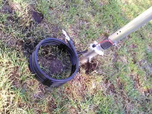
I checked continuity of the feedline and element connections to the center post and to the coax pigtail I was using to feed it while the antenna was on the ground. Now that it was marginally higher in the air, I was anxious to check SWR. I had about eight feet of the pigtail RG-8U hanging down from the feedpoint (at the top of the center post for a number of good reasons) and I couldn’t wait to hook up my MFJ 259B antenna analyzer and see what I had. Very high SWR would indicate a serious problem somewhere. Or that Leo and Steve were exaggerating how broadbanded the antenna was.

Well, I was impressed. The antenna was mostly better than 2:1 across all bands. 20 meters was a bit high at the upper end of the band. Still, I thought that was acceptable considering that the antenna was only about ten feet off the ground, five feet above the deck, and seven feet above a metal patio table.

Without expecting much, I hooked up my 100 feet of RG-8X that I keep on a run from the shack to outside, just to try out various projects. Then I went inside to give it a whirl on the air. Well, I could easily see directionality and front-to-back. On some signals, it was already the best antenna, but on others, one of the wires or the vertical did better. Still, it seemed to work on all five bands without sparks or smoke. I worked a couple of stations, just to make sure, including the Slovak Republic on 17 SSB barefoot and Croatia on 20 SSB with 600 watts.

Performance

I compare antenna performance to the first time I saw color TV as a kid. I was perfectly happy with my old black-and-white TV picture until I saw the Tournament of Roses parade on my grandmother’s new RCA. Never mind that the “colors” were mostly red and green and the picture was swirling all over the place. It was so much better than what I had before that I thought it was the best it could possibly be.

Anecdotal evidence of an antenna’s performance is shaky, too. If we spend thousands of dollars on a sky full of metal, we tend to think it is the best aerial ever erected by man. Same if we bleed and sweat building something from scratch. Still, I have really tried to remain subjective, and to compare my homebrew hex to the other antennas.

On a dreary October day, we raised the antenna to the top of the 43-foot tower (I decided not to use all the sections I had and mounted a damaged section in the concrete base for a base section.) I hired a ham who is also a professional tower guy to help me. We raised it with a pulley and rope with me pulling from the ground and him guiding it up the side of the tower and preventing it from snagging. This is a relatively delicate operation, so have help who know what they are doing. Standing on the rotor plate (and with his climbing belt safely attached to the tower), my friend lifted the beam up and set it down onto the original five-foot mast. He replaced the bolt beneath the baseplate, through the mast and center post, and bolted it tightly.

I use a Ham IV rotator, which is very much overkill, but it happened to be the one I had. The installation as I did it puts the baseplate at about 47 feet and the 20-meter element at about 50 feet.

So, does it work? Absolutely! I used the beam as much as I had time to in the CQWW SSB contest, listening to stations with the beam and then switching, in turn, between the G5RV, the vertical (ground-mounted Hustler 4BTV with 85 radials under it), the skywire horizontal loop, and the ladderline-fed dipole. The beam, when properly aimed, beat the latter two antennas every time on 20 through 10. The G5RV was typically 2 to 3 S units below the beam on 20 and 17 but not even that close on other bands. The vertical was about the same as the G5RV on 10, 15 and 20 for DX but was considerably below the beam stateside and into the Caribbean and South America.

I had been trying to snag the VU7 in Lakshadweep since they first fired up but had not even been able to hear them well enough to work them. With the beam, I got them on the second call on 17-meter CW. Better propagation? Maybe, but I still could not hear him well enough to work him -- much less break the pileup -- on any of the other antennas. The same thing happened with VK9DWX on Willis Island in the South Pacific. When I log a contact, I note which antenna I’m using and whether or not I’m running the amp -- 600 watts PEP SSB, 400 watts CW. On the entry for VK9DWX I wrote next to “Hex” the note, “Thank goodness…could not even hear him with other antennas.”

I have also had several very nice ragchews with stations all over Europe. I know propagation has been better lately, but again, I checked the other antennas and the wire beam was better -- both ways, transmitting and receiving. Just today, as I was writing this article and in the middle of the day, I heard VQ9RD on Chagos Island in the Indian Ocean on 20 meter SSB. There was a pretty good pileup already but I called once and got him.

Seems like that happens more and more lately. My imagination? Maybe. But some of it has to be my funny-looking rose trellis digital TV antenna.

So there’s the hated “anecdotal” report on the antenna’s performance. It seems that many of the guys who build this antenna become almost evangelical about it, and I’ll avoid claiming it to be any more than a small, two-element compromise antenna. But somehow, it does seem to perform better than it has any right to do, considering its size, weight, cost, wind load, and ease of construction.

Let me make this suggestion, though. If you want a good, light, small antenna that offers excellent SWR, good front-to-back and side rejection, and decent gain over a dipole or vertical across five ham bands, and one that will not have you standing at the window, breathlessly watching it every time the wind blows, then consider this one.

If you don’t feel like building one, read the reviews on the Traffie Hex-beam and decide if it is for you.

If you want to build one yourself, go to the sites of K4KIO for instructions and G3TXQ for the theory behind the antenna.

If you don’t have any of the parts and want to buy a full kit, visit the Max-Gain or WI4USA site and learn more.

If you have or can acquire everything else and want to get a good deal on spreaders and/or baseplate, visit the Max-Gain or W4RDM web sites. If you want to gather the stuff together yourself, do not hesitate.

Put one of these things together, put it up on a push-up mast or light tower, rotate it with a TV rotator, and join the rest of us “hex nuts” having a blast with our odd-looking, upside-down umbrellas.

Read more...

An unloaded vertical as a multi-band HF antenna

An unloaded vertical as a multi-band HF antenna

This article explores the performance of an unloaded vertical as a multi-band HF antenna.

Introduction
A system view
Components of an antenna system interact with each other in a complex way, and it is important to analyse the entire antenna system (radiator, earth, transmission line, balun, ATU etc) to obtain a correct nderstanding of how the system works overall.

Acceptable loss
Real antennas are a compromise between performance and practical limitations or economies of implementation.

Each implementer must make a judgement of system loss that is acceptable to their compromise solution. Generally, one expects to accept higher losses in a multi-band antenna system as part of the trade-off for frequency coverage. For average situations, it should be possible to implement multi-band HF antennas with not more than 3dB of system loss on any required frequency. For the purpose of this article, 3dB is regarded as the maximum acceptable system loss, that is at least 50% of the transmitter output power is radiated.

Earth system loss
The models here are based on a vertical of 20mm diameter aluminium tube mounted at ground height, and a system of shallow buried radials.

The performance of real radial systems is very dependent on soil parameters. The models in this article assume a earth system that contributes an equivalent bulk resistance of 10 ohms at the feed point, which is realistic for moderate to good soil and a radial system of 16 or so shallow buried radials.

Tuner loss
All the models use an L Tuner with practical Q values for practical least tuner loss. Other tuner configurations (such as the popular T Tuner) will usually exhibit higher loss. Many commercial T Tuners use small variable capacitors and with extreme loads at low frequencies do not achieve the low losses shown here for a L Tuner.

10m (33') high vertical

This section explores a 10m high vertical of 20mm diameter aluminium tube mounted at ground height, and a system of shallow buried radials, and the following variations in feed line and impedance transformation:
15m of RG58C/U feed line from the antenna base to an ATU at the tx;
15m of RG213 feed line from the antenna base to an ATU at the tx;
15m of Belden 8222 twin line from the antenna base to an ATU at the tx.
15m of RG58C/U feed line from the antenna base to an ATU at the tx

This configuration is a basic way of adapting and connecting a vertical antenna to the transmitter.

Fig 1: 15m of RG58C/U feed line to an ATU

The configuration results in high VSWR operation of the transmission line at most frequencies, causing high transmission losses. Tuner losses are insignificant, assisted somewhat by the transmission line losses. The antenna system has unacceptable losses on all but two bands (40m and 15m), and the antenna is probably only suitable for use on the 40m band because of the dominance of high radiation angle lobes on the 15m band (and above).
15m of RG213 feed line from the antenna base to an ATU at the tx

The performance of the previous configuration can be improved using a lower loss transmission line. Fig 2 shows the system losses using 15m of RG213 feed line.

Fig 2: 15m of RG213 feed line to an ATU

The configuration results in high VSWR operation of the transmission line at most frequencies, causing high transmission losses. Tuner losses are insignificant, assisted somewhat by the transmission line losses. The antenna system has unacceptable losses on all but four bands (40m, 30m, 15m and 12m), and the antenna is probably only suitable for use on the 40m and 30m bands because of the dominance of high radiation angle lobes on the 15m band and above and above.
15m of Belden 8222 twin line from the antenna base to an ATU at the tx

This configuration uses Belden 8222 70Ω twin-line which (although obsolete) was promoted in this application in a recent Amateur Radio magazine article (Jan 2006). It appears its use was inspired by the myth that open wire line is necessarily better than coax in any high VSWR application.

The use of an open wire feed line in this application is certain to result in significant imbalance in feed line current and radiation, but the extent and effects of radiation will depend on the routing of the feed line and ground parameters. This model ignores the radiation from the feed line (based mainly on the idea that power radiated anywhere is not lost and arguably useful), but models the power lost loss within the feed line.

Fig 3: 15m of Belden 8222 feed line to an ATU

The Amateur Radio magazine article mentioned earlier used a feed line length a little less than half that used here, so the feed line losses in that case would be just a little more than half of that shown here (feed line loss is proportional to length ONLY when VSWR is low), eg at 3.5MHz the loss in 7m of 8222 would be 6.3dB against the 11.9dB shown here for 15m length.

It can be seen when comparing Fig 3 with Fig 1 that the 8222 feed line line loss is a little worse than RG58C/U and delivers acceptable losses only on 40m (with losses of 2.3dB). At 3.5MHz, the loss is 16dB which means that 2.5% of the transmitter output power is radiated. It does not qualify as an efficient multi-band antenna, nor as as acceptable single band antenna.

Analysis
Poor performance at lower frequencies is a result of:
the radiation resistance falls at lower frequencies as the radiator becomes shorter with respect to the wavelength;
more of the energy is lost to the equivalent earth resistance as the radiation resistance becomes smaller at lower frequencies; the feed point impedance becomes highly reactive at lower frequencies;
the feed point impedance causes very high VSWR on any practical feed line, increasing feed line loss; and
the ATU is presented with extreme loads, increasing ATU losses.

As an illustration of why a system view must be taken, consider an approach to "fix" the high line loss in Fig 1 by using a much lower loss line. At 3.5MHz, using Andrews LDF6-50 Heliax, the transmission line loss is reduced to less than 2dB. That seems to be an improvement, but is it? The impedance now presented to the tuner (0.38-j10.55Ω) would result in tuner loss of close to 10dB for a typical commercial T-Tuner with 200pf variable capacitors, giving a total system loss of 4.1 (ground loss) + 1.8 (line) + 9.7 (ATU) or 15.6dB which is 4dB worse than the RG58C/U configuration.
A better configuration for the low HF bands - 13m (43') high vertical

Radiation pattern
As the electrical length of the vertical increases (eg at higher frequencies), the radiation pattern spreads into multiple lobes, and more of the power is radiated at relatively high angles, which may be undesirable, especially on the higher bands.

A compromise design to cover 80m through to 20m is to choose a greater length that is not more than about 0.6λ at 20m for best radiation pattern, and the additional length will increase radiation resistance on the 80m band for improved efficiency. A length of 13m has been chosen for this improved configuration.
Antenna efficiency

The power delivered to the base of the antenna is divided amongst three main equivalent RF resistances, they are:
the earth system RF resistance;
the conductor ohmic RF resistance; and
the radiation resistance.

The first two of these are dissipative, that is the energy delivered to them is lost as heat. Energy delivered to the radiation resistance is converted to a radiated electromagnetic wave.

This model uses 20mm aluminium tube, and the radiator conductor loss at 3.5MHz is 0.2% of the power delivered to the feed point, or 0.01dB. The equivalent RF loss resistance of the radiator is too small to significantly affect the results and can be approximated as 0Ω. Such an antenna will usually require a larger tube diameter to be self supporting and to survive winds, in which case the losses will be even lower.

As explained earlier, a fixed 10Ω equivalent series earth resistance is used to approximate a typical good earth system.

Fig 4 shows the modelled radiation resistance on a logarithmic scale.

Fig 4: 13m high vertical radiation resistance
Fig 6: Array Solutions balun recommended for the Zero Five 43' vertical

Fig 7: 13m high vertical, 4:1 balun, 15m of LMR400 feed line to ATU / TX


Not that at frequencies where radiation resistance falls below about 30 ohms, earth loss degrades performance significantly.

The radiation resistance varies from 0.8Ω at 1MHz to more than 1500Ω around 11Mhz (See Fig 4).

The radiation efficiency at the antenna base (ie the power radiated to the power lost as heat) is Rr/(Rr+Rc+Re) where Rr is the radiation resistance, Rc is the radiator conductor RF loss resistance (approximately 0Ω), and Re is the equivalent earth resistance (10Ω for the models). Radiation efficiency at the antenna base varies from a low of 7% at 1MHz to almost 100% at some frequencies. Losses in Re and Rc are shown as "Ant Ground" in the blue area of the graphs below.

Some of the power developed in the radiation resistance as used here is lost in reflection of waves from the ground so the total power in the far field will be somewhat less.

Impedance transformation
The feed point impedance is not a suitable load for most transmitters, nor is the feed point usually immediately adjacent to the transmitter, so further losses are incurred in transforming the impedance to a suitable transmitter load impedance and conveying energy from the transmitter to the antenna feed point.

This configuration transforms the feed point impedance to suit the characteristic impedance of the transmission line in order to minimise feed line loss. 
Transmission line efficiency

The loss in transmission lines is increases above the specified matched line loss when they are operated with VSWR greater than 1. The exact increase depends on the line parameters, the load impedance and frequency.

To manage transmission line loss, this configuration uses a remote antenna tuner located at the base of the antenna so that the transmission line operates at close to unity VSWR at all operating frequencies. Modern automatic tuners are ideal in this application, and very convenient when fully integrated with transceiver controls and logic.

This strategy yields transmission line loss of less than 0.36dB over the design range 80m to 20m. This is a marked contrast to line losses of up to 7.6dB over the same frequency range in Fig 2.
Performance

Fig 5 shows the performance of the better configuration.

Fig 5: 13m high vertical, remote ATU, 15m of RG213 feed line to TX

Loss is less than 1dB on bands 40m to 20m, and 3dB on the 80m band.
In practice

An antenna similar to the better configuration described above has been in use at my Narooma location for over a year with satisfactory results. The antenna tuner was an Icom AH-4 remote automatic antenna tuner which integrates with the IC706IIG transceiver. The earth system was somewhat abbreviated (due to physical constraints) and measurements indicated an RF earth system resistance of around 20 ohms on 3.6MHz which would degrade efficiency at that frequency by a further 3dB than shown in Fig 5.

Making QSOs is not evidence that an antenna performs as well as it could or should under the circumstances!
ZeroFive feed configuration Original

A correspondent asked whether the feed configuration of the ZeroFive "43 foot MULTI-BAND 10 to 160 meter vertical" works better than the remote tuner configuration described above. The Zero Five 43' vertical is a 13.1m high unloaded ground mounted vertical with shallow buried radials, and so the antenna is somewhat similar to the 13m vertical described above.

The ZeroFive "43 foot MULTI-BAND 10 to 160 meter vertical" is fed at the base with a Array Solutions AS-200-T 4:1 balun rated at 5kW from 1.5MHz to 30MHz. As both the antenna and the feed line are unbalanced, it is not obvious why a balun (as opposed to an un-un) is used, nor do the installation instructions show the connections.


Fig 6 shows the internals of the balun and its connections courtesy of ES1TU. The left hand terminal is to the base of the vertical, and the right hand terminals are to the ground system. In this case, the coax feed to the shack is buried along with one of the green/yellow earth conductors.

A voltage balun is quite unsuited to this application. This arrangement puts the coax shield at a voltage approximately half the voltage at the the base of the vertical. This will drive common mode current on the coax outer, undesired feed line radiation, common mode losses, modification of the feed point impedance and conducted RF entering the shack depending on the feed line route. The outcome will be variable, depending on the path of the coax (eg topology, burial, soil types) and coupling with nearby conductors (eg radials, equipotential bonding, lightning conductors).

The manufacturers do not explain how this works or is intended to work. The configuration defies sound design principles.

In answer to the correspondent's question on the Zero Five / Array Solutions feed arrangement; no, an ideal 4:1 voltage balun and ATU at the tx is not likely to be as good as the remote ATU configuration, and the recommended 4:1 voltage balun is not well suited to the application.
Current balun

A 4:1 current balun does not drive the coax with common mode current in the way that a voltage balun does.

The following models assume it is an ideal 4:1 transformer with very high common mode impedance (ie a current balun).


Fig 7 shows the modelled loss for the 13m vertical with 15m of LMR-400 feed line (as recommended by ZeroFive) and an ideal 4:1 balun at the feed point to an ATU adjacent to the transmitter.

Loss is less than 1.4dB on bands 40m to 20m, and 4dB on the 80m band. The loss on the 160m band is 12dB which questions rating of a similar antenna as suited to 160m. Note that at 1.8MHz, the feed point voltage at 1.5kW would be 8000V RMS which is impressed fully unbalanced on the output terminals of the balun.

System loss with a practical transformer is likely to be worse than modelled here with an ideal balun, especially at extreme impedances (VSWR>5) which occur in the 160m, 80m, 30m, 20m, and 12m bands .

The extreme impedances encountered are likely to be well beyond the capability of the internal tuner in most transceivers, and so an external high power low loss tuner is advised. Losses in most commercial T-tuners will be higher than the L match modelled, especially on the lower bands (80m, 160m).
Unun

A 4:1 unun would work similarly to the current balun case above.

The supplied 4:1 voltage balun could be converted to a 4:1 unun. Referring to Fig 6:
Remove the wire from the socket centre pin to the left hand screw terminal.
Move BOTH wires connected to the socket body to the socket centre pin.
Install a wire from the socket body to the right hand screw terminal.
Label the right hand side terminal GROUND. 

There may be benefit in installing a common mode choke (1:1 current balun) on the coaxial feed line outside the radial field if common mode current entering the shack is a problem. Note that burial of the feed line would usually reduce common mode current entering the shack to a safe level.

Conclusions
Earth system losses are very significant with short Marconi type antennas on low HF bands, and may be the component of loss that is most difficult to minimise.
Transmission line loss is potentially very significant, and can be minimised with careful system design.
ATU losses are low except for low frequencies where extreme loads may be presented to the ATU.
A vertical longer than about 0.6λ will result in more of the power radiated at relatively high angles, which may be undesirable, especially on the higher bands.
The components of an antenna system interact in a complex way, and the entire antenna system must be analysed as a system to understand its performance.
The Zero Five / Array Solutions recommended 4:1 voltage balun feed does not appear to be a better arrangement and is difficult to rationalise.

Read more...

A Simple But Effective Low-Band Base Antenna

A Simple But Effective Low-Band Base Antenna
Since childhood I have been in search of the best performance out of an antenna. It began with my first folded dipole hung between a tree and the house. Later I fashioned coils and inserted them inline to increase the electrical length of the antenna. My love for building antennas has grown ever since.

Back in the 70's the Los Angeles County Sheriff was still on low band at 39mHz and I knew from experience that a CB antenna worked great when tuned just by shortening the radiator. Propagation of low band signals is great, including "skip." But here at my new home in Big Bear, California -- where birds sing and the skies are blue -- I didn't want to have an antenna farm on the roof. This meant a vertical antenna without ground radials.

The Half-Wave Coaxial Antenna

An effective emergency antenna used by many amateur radio operators is fashioned by making a 1/2 wave antenna using coaxial cable. This is done by pulling the braid back 1/4 wave length over the cable insulation. You may then tack the center conductor up on a wall and plug into a scanner. Although it works, this isn't a permanent antenna. Enter the home-made, full-size solution. Some of you may recognize this as the type of antenna that CHP uses. Yep.


This version is tuned for 40mHz and stands 11.3 feet tall. Made from schedule L and M copper pipe, this version is better able to withstand high winds. Using an antenna analyzer shows a 1:1 SWR. Perfectly tuned!

Construction

Construction of this antenna is very straight-forward and requires only a few inexpensive parts.
1 - 10ft. Length 1" Copper Pipe
1 - 6ft. Length 1 1/2" Copper Pipe
1 - 1" Cap
1 - 1 1/2" Cap
1 - 9ft. CB Whip 3/8" (RS)
1 - 3/8" Feed-Thru (RS)


Begin first by drilling out the copper end-caps to accept the feed-thru adapter from radio Shack. The adapter comes apart to expose a slightly raised and electrically shielded 3/8" stud.

When drilling the caps make every effort to drill the holes in the exact center of the caps. This will allow a uniform distance from the pipe when finally attached.

Slip the smaller cap into the larger cap and affix the 3/8" feed-thru adapter.


Now that the end-caps have been prepared you will need to cut the copper pipes to length. The 1" pipe needs to be cut to 86" A pipe cutter or hacksaw will work fine. The 1 1/2" pipe will be cut to 68". Once this has been done you are ready to assemble the antenna. Simply insert the 1" pipe into the 1 1/2" pipe. Slip your quality RG-8 or better coax into the 1" pipe and feed it up to the other end. Make sure that you have no burs or sharp edges from cutting either pipe.

NOTE: This antenna can be cut for the 6 meter amateur radio band and makes an excellent repeater antenna. The formula for the elements is ((460/f) / 2) where f is the frequency. At high elevations it works better without a ground plane. At lower elevations you may add a 1/4 ground plane below the sleeve and achieve about 3dB gain. Bob - AF6D


Once this has been done you are ready to assemble the antenna. Simply insert the 1" pipe into the 1 1/2" pipe. Slip your quality RG-8 or better coax into the 1" pipe and feed it up to the other end. Again, make sure that you have no burs or sharp edges from cutting either pipe.

Next, we need to use quality duct tape at the bottom of the 1" pipe. Measure 17" up from the bottom and begin wrapping 2" wide duct tape around the pipe until it is about 3/8" thick or so -- just thick enough so that when the 1 1/2" pipe is pulled over it it is snug and electrically insulates. Just above this wrap make an identical wrap so that you have about 4" of duct tape. As an option you may use wrap-around weather sealing foam tubes.


We are now ready to slide everything together. Grab your end-cap assembly and snuggly attach the PL-259 connector on your cable to the SO-239 socket on the feed-thru adapter. Make a good, solid connection. You probably don't need to worry about trying to put tape around it.


Next, slip the 1" pipe up into the 1" end-cap. Then slip the 1 1/2" pipe up into the outer 1 1/2" end-cap. Note in the photo that we have drilled a small hole. This hole is drilled so that it goes through both end-caps. It should be just large enough to start a 1/2" self-tapping sheet metal screw. This screw will then be tightened down. Once tightened, it will just touch the outer ring of the PL-295 connector inside the pipe. This will ensure solid electrical contact all the way through.

Finally, take the 102" CB whip antenna and cut it down to 68". Once cut, attach it to the top of the feed-thru adapter. You are now ready to put your stick in the air!


The last steps require that you use mounting hardware sufficient to mount this antenna to a vertical pipe. Your situation will determine what you use. I used 2 1/2" muffler clamps and attached the antenna to a 10 foot push-up. Do not over-tighten the clamps because the copper pipe will collapse. In fact, better clamps to have used would have beenTV mast type because of the way that they wrap around with teeth.

The absolute final step for me was to use non-conductive paint and spray the entire antenna a nice shade of green to match my mountain community home. Choose a color that you like and spray -- this is copper and needs to be covered.

This design is the heavy-duty design and should provide years of unattended reception in even the harshest weather. This antenna is on its 5th winter at 7,000 feet up in snow country.


Read more...

Multi Band Vertical 10-80 metres

Multi Band Vertical 10-80 metres
I
I'd thought I'd like to try a HF vertical

I've read about them, heard various reports on them, and read some more .... and then I thought I'd give one a try. It is a lot lighter than I'd thought it would be. Looks very impressive in a small suburban backyard. I used clothes hoist insulated nylon cord/rope for the three guy wires anchored via tent pegs. It went up quite easily - in a no breeze wind condition. When guyed, quite stable when the wind did blow and rain, too.

 
The mid-section.

Here you can see the 40 & 80 metre loading coils and capacitors. These are very tricky to tune. (3 to 5mm movement at a time!) The frequency spread is very narrow because of the high Q of this design and benefits from use of an antenna analyser in the alignment process. The wire is 5mm aluminium, the brackets made from 10mm aluminium and the nuts, bolts and washers are stainless steel. The piston capacitors are rated for 4kW! (Not that I would be using that level of RF power!)
Yes. I have a bit of an antenna farm, at times, too! (as can be seen in the background.) I enjoy experimenting and do take an active interest in my hobby.

 
 40M coil and capacitor

Here's another view of how the top bit goes together.

 
Insulated mid-section

Yes. The mid-section is actually insulated. The flat aluminium bar clamps around this section for support. The 40 & 80M coils and capacitors connect to this "bar".

 
 The 80M coil and capacitor.

This shows how the 80M bits.

 
 The 80M capacitor clamp.

This shows the lower clamp for the 80M capacitor. You can also see the aluminium tube joiner in place. This is secured via 2 + 2 bolts with captive head nuts.

 
 Ground level.

We can see the 75 ohm coax matching section fed to the base connection. The small coil acts as a dc grounded choke. (Also as a static leak!) You may also see a stainless steel bolt with nuts and washers, used for connecting radials, below the connector bracket. (Minimum of 4 per band, is recommended.)


Read more...

Self's building of a HF2V, vertical antenna for 40 and 80m

Self's building of a HF2V, vertical antenna for 40 and 80m

After different attempts with vertical 1/4 Lambda mono band antennas the desire for a vertical multiple antenna was responsible for 40 and 80m with me. However a Groundplane presupposes a good radial net, otherwise it does not work well. I have some fence mats and 10m around the toe am enough wires laid out.

First I regarded the antiresonant circuit Groundplane. There the antiresonant circuit comes to a 1/4 wavelength, related to the higher operating frequency (7 MHz). Afterwards the extension comes for the deeper operating frequency (3.5 MHz). That is, after approximately 10m aluminum pipe or wire is added the antiresonant circuit for 40m, then still another times 10m aluminum pipe or wire for 80m. Overall height is nearly 20m! By the overall height from 20m to brought in in the top (over the 40m antiresonant circuit) a loding coil will reduce. The length reduces substantially, in addition, the range. I rejected the idea an antiresonant circuit antenna to build, since she appeared too long to me. Also build the antiresonant circuit was too tricky, since these achievements up to 750 Watts should stand. Attempts with a coaxial cable antiresonant circuit from RG-58 resulted in that it already warmed up with achievements by 250 Watts and increased then the SWR.

Then I regarded the two-volume Groundplane with multi-volume antiresonant circuits of VK2AZN in the "Rothammel" antenna book. The size and function seemed to me ideally, however I, up to the data in the "Rothammel", did not find concrete building guidances.

My search in the InterNet brought me on the side of EI7BA. He operates a HF2V- reproduction for many years. Also with one great "L" solution for 160m.

The "Butternut HF2V" is a 2 Band vertical antenna for 40 and 80m. With optional extension, also for 30 and 160m, thus the 4 deep Bands. The Butternut is 10m long and stands for instance 1kW transmitting power. The price in Germany amounts to approx.. 350 Euro.

Operational principle HF2V

With the HF2V, simplified, the loading coil for 3.5 MHz on one is described approx. A length of 10m is enough for emitter computed, and measured and over a 200pF condenser uncoupled the resonant frequency of 7 MHz, at the coil.


The condenser sits with a contact directly at the coil. The other contact short circuits the lower part of the coil with an aluminum handle during excitation with 7MHz. During excitation with 3.5 MHz the condenser is high impedance, the jumper is ineffective.

Choice of materials and procurement

Thus I caught to the suitable aluminum pipes to procure. That still to some extent could be done. I had still junk and supplemented this with pipes from the building market. For the top one can use also GFK rods or telescopes.

With the condenser the concerns began. It must have a capacity of 200pF, be current celebration, and exhibit a tension strain of approx. 12kV. There is it in Germany for the "Butternut HF2V" as original spare part of Bencher via Wimo for over 30 Euro. Otherwise I found suitable "Doorknob capacitor" only via the USA import. There postage is more expensive than the part.

But I had good luck. In an InterNet auction I arose (for 6 Euro) 4 new Russian 100pF/16kV condensers. On a ham- flea market lasts perhaps also still another possibility been.

I soldered 2 pieces of these condensers parallel. then 200pF results in 2 x 100pF.


Around the 2 large air coil windings to be able I needed 4 to 5mm to thicken, 15m long aluminum wire. I could not find this aluminum wire until today. There is apparent only 3mm flower wire from aluminum.

First I wound the coil with 1 mm silver wire on 70mm PVC pipe. The silver wire was however too thin and warmed up the top of the coil with 400 Watts of transmitting power rather strongly. Later I exchanged then the silver wire against thicker 6 mm copper wire. With the wire strength applies: The more thickly, the better.

The insulator between the lower and the upper coil is the weak point of the system. PVC is bent in the test due to the coil heating up. Because no suitable insulator from ceramic(s), glass or ev. Teflon was present, decided I for hardwood. That gives the mechanical structure also more stop. The wood should be water resistantly sealed.

Structure


The aluminum pipes plug together telescope-like. The 4 thinner bars of the upper 4000mm are pre-drilled and with 2 tapping screws each per junction point bolted.

3 the thicker pipes within the middle range is slit and with pipe clamps blocked with the circular saw. They result in a length of 3500mm.

The lower part of the antenna is 2500mm long, carries the multi-volume circle and has the feed.


At the feed, which takes place with 50 ohms of coaxial cables, is a coil with 17 turns on 20mm with an approximate length of 140mm. It derives static loadings. The wire should be rigid because of stability. Copper wire with 1 to 2mm is OK. At the lower part of the feed the radial net is attached. Here is to be paid attention to particularly good contacting with a broad ground strap.

The two coils of the multi-volume circle are described above. The capacity is installed weatherproof into a box. The mechanical attachment and contacting take place with screws and nuts/mothers on suitable aluminum strips.


Alignment

First, a good SWR does not state anything over the efficiency of the antenna. On the efficiency decide transition resistances, radial net and losses in the coils.

The alignment of the antenna is only hearing accomplished moderately and with the Transceiver built in SWR- meter.

At the beginning I recommend to measure the two coils 3 to 4 turns longer than necessary. One should make 2 small short circuiting bridges with alligator clips. Thus one can bridge the coil and stop the resonance forwards.

The Transceiver stands directly at the foot of the antenna, attached with a 50 ohm of coaxial cables, on receipt. Its loudspeaker is untwisted strongly and one hears it noise.

First the antenna is adjusted to 7 MHz. Since during excitation with 7 MHz the condenser is low impedance, short circuit and ineffective the lower coil is electrically over the aluminum handle.

On 7 MHz only the upper coil is effective. The upper coil is adjusted with a short circuiting bridge hearing moderately to maximum volume. If the resonance is too deep against 6 MHz, the coil is too long.

On 3.5 MHz both coils are effective. Since the upper coil is already adjusted, it is not changed. The lower coil is adjusted with the second short circuiting bridge hearing moderately to maximum volume. If the resonance is too deep against 3.0 MHz, the coil is too long.

After the hearing moderate adjusting, mutually on both volumes, the SWR with small achievement is examined. With one turns by the standing wave process a tendency at the VFO recognizes. First one adjusts the SWR to 7 MHz, then on 3.5 MHz finely with the short circuiting bridges.

If one changes the upper coil for 7 MHz, also the SWR to 3.5 MHz changes.

If one changes the lower coil for 3.5 MHz, the SWR to 7 MHz does not change .

Now one notes the effective numbers of turns of the two coils. The surplus turns are removed.

With my PVC pipe abt. 70mm diameter I have approx. 10 turns with the upper coil by 210mm length and with the lower 16 turns with 320 mm length.

The renewed fine alignment happens also pushes together or pulls apart the turns on the pipe.

To 7 MHz the resonance characteristic reacts through changes to the coil situation quite slowly-acting, comes from the high range of over 500kHz.

On 3.5 MHz the range is only approx. 50kHz. small changes in the coil changes the point of resonance substantially.

Operational experiences

Still during the alligator clips at the coils hung, I worked in the afternoon on 80m in CW two QSO with German OM's. They confirmed a loud signal. My receipt was excellent. Because I built another antenna on the same day still another, I came only against midnight with the finished selfmade HF2V back on 80m. The old IC-701 sizzled quite loud, a thunderstorm lay in air. On 7005kHz then VK6HD. A call with 100 Watts and the QSO came off. It gave 599 and it was with me also 589. My dear man. I saw later, at the computer , which was VK on 80m for me new country, and which also over 23000 QSO in the log.

On weekend after I went through with the HF2V in the IARU Contest. In the evening hours and at the night I made 336 connections there on 40 and 80m into all continents with 400 Watts.
Read more...

Heil Sound – PRO SET ELITE Microfone

Heil Sound – PRO SET ELITE Microfone


The Basics
The new Heil Pro Set Elite is the ultimate boomset designed for commercial sportscasters, podcasters and amateur radio operators using the newly designed Heil HC 6 wide response microphone element. The new technology of the Heil HC 6 is designed for full range commercial AM or FM network broadcasts or can be adjusted for bright, articulate audio to cut through amateur radio noise and signal pileups. The Pro Set Elite offers dual side, highly efficient speakers mounted in acoustically tuned chambers which produce high rejection of outside noise. The exclusive Heil Phase Reversal feature allows the user to move the signal acoustically, which creates a spatial widening of the sound field that makes it easier to ‘see’ a signal inside a pileup while removing listener fatigue during prolonged use. The headphone’s speakers fold up for easy transportation and storage.

The field-replaceable cushioned ear pads also come with removable cotton covers that can be easily removed for washing. The 6′ coiled cable terminates in a 1/8″ mono plug for the microphone, and a stereo 1/8″ plug for headphone speaker connection. A 1/8″ to 1/4″ adapter is also supplied. The PRO SET ELITE works with all Heil AD-1 adapter cables, which mate with just about every type of amateur radio transceiver.

There are two different models:
Pro Set Elite – 6 contains the Heil HC 6 full range dynamic broadcast element. The HC-6 is designed for commercial broadcast applications; the -3dB points are fixed at 100 Hz and 12.5 kHz, with sensitivity of -57 dB at 600 Ohms output impedance (centered at 1kHz). Using new dynamic technology, the HC 6 response can be equalized to match just about any requirement, from full range commercial broadcasting to serious contest and DXing. Listen to John W5GI as he transmits using the HC 6 into his Flex transmitter and what you are listening to is that signal received on a second Flex receiver.

Pro Set Elite – iC contains the specially designed high performance electret condenser which was designed for low level mic inputs used in many iCOM amateur radio transceivers. The -3dB points are fixed at 80 Hz and 12.5 kHz. The iC element requires + 5 Volts DC phantom power, which all iCOM rigs provide.

Read a review of the Heil Pro-Set Elite at eHam.net

Another review of the Pro-Set Elite

Some state laws prohibit the use of headsets while operating a vehicle. Please check with your local regulations and restrictions prior to usage of this product while operating a vehicle


Read more...

YB8Y – Ohoiew Island OC-221

YB8Y – Ohoiew Island OC-221


oppy, YB8XM plans activity from Ohoiew Island OC-221 as YB8Y between March 20-27, 2012.

QRV all bands / modes. QSL via YB1GJS.

Joppy explains: Ohoiew island is a small island off Kai islands. You can see it with APRS or Google maps – coordinates 132.38.04,9E and 05.41.15,3S.


Read more...

Monday, February 27, 2012

Contester’s Code of Ethics


Contester’s Code of Ethics

II will learn and obey the rules of any contest I enter, including the rules of my entry category
I will obey the rules for amateur radio in my country.
I will not modify my log after the contest by using additional data sources to correct callsign/exchange errors.
I will accept the judging and scoring decisions of the contest sponsor as final.
I will adhere to the DX Code of Conduct in my operating style.
I will yield my frequency to any emergency communications activity.
I will operate my transmitter with sufficient signal quality to minimize interference to others.


Dedicated to improving the skills of amateur radio operators around the world, utilizing education, competition, advancement of technology and scientific research, promoting international friendship and goodwill, and preparing them to better serve society in times of communication need.
World Wide Radio Operators Foundation, Inc.

The World Wide Radio Operators Foundation was created in 2009 by a group of radio operators who saw a need for an independent organization devoted to the skill and art of radio operating.


We believe that amateur radio contests provide a means of testing operating skill and that worldwide contest sponsors can benefit from the support we can provide.

The Directors and Officers of the World Wide Radio Operators Foundation are all well-known and highly-respected radio operators. In addition, each brings a specific skill set and proven track record in his professional career to the management of the organization.

A FOCUS ON OPERATING

Amateur radio is a very diverse hobby. Some amateurs enjoy designing and building their own equipment. Some enjoy the thrill of chasing DX. Some simply enjoy casual conversation with other amateurs in far-off locations. Still others use their skills to provide communications in emergency situations where other forms of communication are not available.

National organizations such as ARRL serve the whole spectrum of pursuits in the hobby. Some clubs and organizations, such as the Northern California DX Foundation, YASME Foundation, and mode-specific groups such as FOC and CWOps, are devoted to specific segments of the hobby. However, no organization exists that is focused on radio operating across all bands and modes.

Until now, many of the elements of modern radio contest operating such as log-checking software, log-submission robots, etc., have been developed and supported by volunteers. Many of the enhancements envisioned for the future will involve considerable expense, and no organization exists to support them.

The World Wide Radio Operators Foundation was created to fill that need.


Read more...

ARRL DX SSB 2012: Propagation Cools as ARRL CW Focused Again on Carribean Contesters

ARRL DX SSB 2012: Propagation Cools as ARRL CW Focused Again on Carribean Contesters

After fantastic worldwide conditions last fall for the CQ WW DX Contests, the sun has not been cooperating so far in 2012, and that was true in the ARRL DX CW test, limiting the best six-band DX propagation to those stations in the Carribean.
And it might well mean the same kind of contest in the ARRL DX SSB, which starts at 0000z March 3 and ends at 2400z on March 4.
It's not to say that Europe and Asia were absent from ARRL CW - far from it. But 10 meter openings to outside of the Carribean were more limited in nature than what contesters experienced late last year.
Sunspot numbers continue to be just average, nothing like the three digit showings that thrilled contesters last fall, leading to hopes for a fast-paced 2012 in terms of contesting, hopes that now seem a bit far away.
As for the ARRL CW scores, John Barcroft K6AM leads all DX stations for now as he ran up 6.9 million points from ZF2AM in the Cayman Islands from 6,568 raw contacts and 353 mulipliers - as he only missed VE4 on 160 meters.
"Conditions were pretty good overall," Barcroft said in his 3830 report, noting good openings all day and into the evening on 15 meters, but more spotlight openings of past years on 10 meters.
Barcroft is about 340,000 points ahead of Andy Faber AE6Y, who ran P49Y to 6.6 million points.
The low power category was also dominated by stations in the Carribean, with N3AD the leader from VP2MMM at 4.9 million points.
Back in the US and Canada, the review was mixed - lots of activity, but not the wide open bands many had been hoping for in 2012.
"Interesting conditions," remarked Scott Redd K0DQ, who operated from WW1WW, notching 6.7 million points for the top single op score so far.
The low power lead is up to the log checkers, as Maury Peiperi W3EF has a lead of just 36,000 points on defending champ Ed Sawyer N1UR, who almost pulled off another top score despite suffering from the flu.
"10M was very poor here considering how fun in was through the end of last year," Sawyer said on 3830, adding that he found "Friday night 160 and 80 were terrible and even Sat night was only so so."
"Unlike the CQ WW CW contest, the contest wasn't quite as much fun, mostly due to the relatively degraded conditions compared to last fall," said John Dorr K1AR on 3830.
"However, working nearly 3K QSOs is still a good time by any definition," Dorr added, as he churned out 4.3 million points in the Unlimited category.
An auroral disturbance during the contest didn't help conditions for some in the northern latitudes, both in Europe and the US and Canada.
"Conditions on the low bands the first night, pretty poor but even poorer was 10 M the second day," said Mark Pride K1RX, whose Multi-Multi team ran up over 10 million points.
"Oh well," Pride said on 3830.
The Multi-Multi lead in ARRL CW right now is in the hands of Team W3LPL, but only by 170,000 points over Team K3LR.
W3LPL had 8,073 contacts and 678 mults; K3LR edged them in mults with 683, but had fewer QSO's at 7,929.
"Its amazing how two top scoring teams can compete for 48 hours under considerably different propagation conditions and submit scores within just one percent of each other," said Frank Donovan W3LPL afterward.
W3LPL grinded out only 598 contacts on 10 meters; they had almost three times that many in CQ WW CW with 1,786 QSO's.
For those doing only 10 meters, it was a frustrating weekend.
"It was a tough slog," said Pete Stafford K2PS, who didn't find much joy from Washington, D.C.
"I was hoping to reprise my terrific experiences from the recent CQWW and ARRL 10 Meter contests by doing a single band 10 meter, LP effort," Stafford said on 3830, but he only managed 176 contacts and 67 mults.
But - as a reminder to all of us - while that might not seem like much, it has Stafford at the top of claimed scores in his category.
Down the East Coast to North Carolina, Bill Tippett W4ZV checked in with the best 10 meter single band score, as he found 825 QSO's and 105 multipliers.
"Aurora Saturday caused some interesting openings over the North Pole and also caused Asia to skew over the South Pacific," W4ZV reported on 3830.
The 10 meter leaders were in the Carribean as you would expect - with HK1R and J39BS leading the high and low power categories.
Will that be the story for ARRL SSB? The bands may be more like ARRL DX 2011 than last fall, but it doesn't mean it won't be a fun time to contest. The ARRL DX SSB Contest begins at 0000z March 3 and ends at 2400z on March 4
Read more...

Sunday, February 26, 2012

Welcome to LCWO.net - Learn Morse Code (CW) Online!


Welcome to LCWO.net - Learn Morse Code (CW) Online!

At LCWO you can learn Morse telegraphy (CW) online in your browser. You don't need to install a program on your computer, and you always have your personal settings available, from any computer on the globe with an internet connection. You can also easily track your progress by means of different statistical functions.
Sign up for a free account (or use username "test", password "test" to play around) and start learning or improving your CW today

Features

- Koch Method CW Course
Highscores — compare your results with others
- Speed Practice (Code Groups, Plain Text Training, Callsign Training, Word training)
MP3 practice files (Download)
Convert text to CW (does not require a login)
Forum for user discussions and feedback
User groups
WAE QTC training
- more to come soon...

About LCWO - Learn CW Online

This site, Learn CW Online (LCWO), was established in May 2008 by Fabian Kurz, DJ1YFK (Impressumprofile), hoping to make learning and practicing CW (Morse code) as easy and effortless as possible.
LCWO is under constant development; all comments and suggestions are welcome. To get in touch with the author, use the contact form or send an email to help@lcwo.net. For general questions and discussion, feel free to use the forum. Thanks to all the users who contributed to the project so far. Without all the feedback the site wouldn't be what it is today!
Using LCWO is and will always remain free of cost. We are not interested in monetary donations.

Translators

Many thanks to following persons for translating the user interface to new languages:
If you like to help to translate LCWO to another language, please get in touch with Fabian, DJ1YFK via email. Thanks!

Spread the word!

If you like to link to LCWO from your website or blog, you may want to use one of the following banners or buttons. Also high resolution logos (b/w) are available for QSL cards.
Banner, 468x60px:
[LCWO Banner]

Buttons, 80x15px:
[LCWO Button 1]  [LCWO Button 2]

Logos for QSL cards (ZIP file with several formats, PDF, EPS, PNG):
[LCWO print logo]

Read more...

QRQ - yet another CW trainer (Linux, Unix, OS X, Windows)

QRQ - yet another CW trainer (Linux, Unix, OS X, Windows)

Current version: 0.3.0 - December 18th 2011 - see ChangeLog - Downloads.


qrq is an open source Morse telegraphy trainer which runs on several operating systems (Linux, Unix, OS X and Windows), similar to the classic DOS version of Rufz by DL4MM.
It's not intended for learning telegraphy (check out LCWO or have a look at radio.linux.org.au for CW learning software), but to improve the ability to copy callsigns at high speeds, as needed for example for Contesting.

How to use it

Using qrq is simple: qrq sends 50 random calls from a database. After each call, it waits for the user to enter what he heard and compares the entered callsign with the one sent. If the callsign is copied correctly, the speed is increased by 10cpm / 2wpm and full points are credited, if there were mistakes in the callsign entered, the speed decreases by 10cpm / 2wpm and (depending on how many letters were correct) only a fraction of the maximum points are credited.
A callsign can be heard again once by pressing F6, hitting F10 aborts the attempt.
The possible speed ranges from 20cpm (4wpm) to infinity, the initial speed can be set by the user (in ~/qrq/qrqrc or in the settings menu, F5).
Additionally, there are several training modes available. Arbitrary databases of callsigns or words can be loaded, it's possible to practice at a fixed speed, etc.

Toplist

There is a simple toplist function in qrq which makes it possible for the user to keep track of his training success or to compare scores with others.
A small Perl script (qrqscore) can be used to upload your best score to the the qrq toplist, and to synchronize your local toplist with the online list. If Perl is not available, scores can also be sent by email to the author.
Note that there is no checksum or other mechanism to verify the scores, it relies on your honesty.
As of version 0.0.7, the toplist file also includes a timestamp of the attempt, which makes it possible to keep track of your training progress. Pressing F7 generates a graph score vs. date. (Gnuplot required.)

Configuration

All settings are saved in the configuration file qrqrc (in the current directory or ~/.qrq/ on Unix). You may edit it before running qrq for the first time, but most settings can also be changed in the configuration menu (F5, also works during attempts).

CW tone generator

Special care has been taken of the CW tone generator. In order to avoid key clicks, the CW signal edges are formed as a raised cosine impulse. The rise- and fall times can be set individually to any value (in milliseconds); an adaptive mode allows to use different times depending on the current speed. This graph (produced with GNUplot) shows a dash at 500CpM/100WpM with 5ms rise time and 15ms fall time (too much for real CW, just for demonstration purposes), at a samplerate of 44.1kHz.
OSS, PulseAudio, Core Audio (OS X) and WinMM are supported methods for sound output.

Download, License

Of course qrq is free software (free as in beer and free as in freedom) and published under the GPL 2.
The current version is 0.3.0 and can be found in the download-directory.
qrq is also available as a package in different formats, thanks to the work of the respective maintainers.
FormatLinkMaintainer
sourceqrq-0.3.0.tar.gz-
FreeBSD portports/comms/qrqDiane, VA3DB
Debian debqrqKamal, KA6MALSteve, AI4QR
Ubuntu debqrqvia Debian
Mac OS Xqrq-0.2.1.dmgMarc, KB1OOO
Windows Installerqrq-0.3.0.exe-

Author, Contact, Feedback

qrq was written by Fabian Kurz, DJ1YFK.
Marc Vaillant, KB1OOO contributed code to make it work under Mac OS X.
Lukasz Komsta, SP8QED contributed code for the native Windows version.
I am always interested in any kind of feedback concerning qrq. If you have any suggestions, questions, feature-requests etc., don't hesitate a minute and contact me via email.


Read more...